background image

CALIBRATE

CHANGE

RESULTS

RUN DETECT

CALIBRATE

SYSTEM FAULT

RUN ERROR

I S C

L o m a  S u p e r s c a n  M i c r o

SETUP

ENTER

CANCEL

9

MENUS A to Z

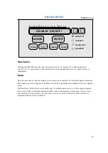
Description:

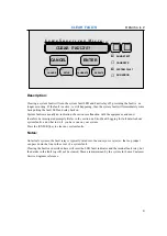
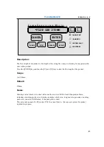
Clearing a system fault will turn the system fault LED and Fault relay off, providing the fault is  no
longer occurring. If the fault is active, ie. still happening, then the system fault will immediately come
back putting the fault LED and relay back on.

System faults are usually an indication of a serious malfunction with the equipment, and must
therefore be investigated promptly. Refer to the section on Error/Fault Logging for full details about
system faults, and what to do if  you have one on your system.

Press the [ENTER] key to clear any system faults.

Notes:

On failsafe systems, the fault relay is typically wired into the conveyor or reject so that no product
can pass down the line in the event of a system fault.

Clearing the faults as described here will reset the LED fault indicator and the internal fault relay, but
the details in the fault log will not be cleared. These are maintained by the system for Loma Customer
Service Engineer reference.

CLEAR FAULTS?

CLEAR FAULTS

Summary of Contents for Superscan Micro ISC

Page 1: ...resents the amount of production statistics that will be accumulated before they are transmitted down the serial link to a printer or computer and then reset to zero Press the ENTER key and then the a...

Page 2: ...t to 18 30 hours This would mean that the batch statistics would be reset and transmitted down the serial link every hour at half past the hour Press the ENTER key and then the or keys to adjust the b...

Page 3: ...TS PACKS Description Press the ENTER key and then the or key to select between time or packs for the batch interval Scope TIME or PACK Default TIME Notes A photo eye PEC must be fitted if the batch in...

Page 4: ...MENUS A to Z Description The date and time specified within this menu are used to time stamp the data in the contaminant fault and error logs and also on the printed reports Press the ENTER key to gai...

Page 5: ...ransmitted down the serial link upon completion of a calibration cycle only if report is enabled in the serial link menu and the calibration report is enabled in the Report Options menu ANY DISPLAY SA...

Page 6: ...he ENTER key for the selection to take effect Warning Messages CHANGING TO This message is always displayed to indicate that a product change is taking place The new product name and number is display...

Page 7: ...DETECT CALIBRATE SYSTEM FAULT RUN ERROR I S C L o m a S u p e r s c a n M i c r o SETUP ENTER CANCEL 7 MENUS A to Z Description Press the ENTER key to clear the entries in the contaminant log CLEAR C...

Page 8: ...r will turn the run error LED and Auxiliary relay off if it is configured for run error indication providing the error is no longer occurring If the error is active ie still occurring then the run err...

Page 9: ...ction with the equipment and must therefore be investigated promptly Refer to the section on Error Fault Logging for full details about system faults and what to do if you have one on your system Pres...

Page 10: ...to view the compensation and signal level values the and keys to adjust the compensation value The compensation value is displayed on the left hand side of the display and the signal level on the righ...

Page 11: ...e ENTER key to move into this menu Notes Once the Configuration menu has been entered the detector will stop detecting and the Run Detect LED will go out If the detector suffers from memory corruption...

Page 12: ...to Z Description From within this menu the contaminant log can be viewed cleared and if the reports option is enabled a contaminant report sent down the serial link See the View Contaminants Clear Co...

Page 13: ...lly to a printer Note To gain access to this command the report must first be enabled in the Report Options menu CONTAMS REPORT SAMPLE REPORT LOMA SUPERSCAN MICRO METAL DETECTOR METAL CONTAMINANTS REP...

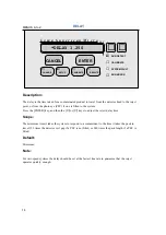
Page 14: ...e PEC if one is fitted to the system Press the ENTER key and then the or keys to adjust the reject delay time Scope The minimum time it takes the system to respond to a contaminant to the time it take...

Page 15: ...he reject device has been disabled this menu item is replaced by the Enable Reject command This menu entry will not appear if the Reject Out of Run option has been enabled in the User Options menu The...

Page 16: ...calibration setting for dry products during a calibration cycle In cases such as these it may be necessary to set this setting to YES so that the detector is forced to work in the Dry mode see Workin...

Page 17: ...hat the reject device is activated for once the reject device has been reached by the contaminated product Press the ENTER key and then the or keys to adjust the reject dwell time Scope 0 025 to 49 99...

Page 18: ...o m a S u p e r s c a n M i c r o SETUP ENTER CANCEL 18 MENUS A to Z Description This command can be used to turn the reject mechanism back on after it has been disabled see Disable Reject command Pre...

Page 19: ...Error log to be transmitted down the serial link typically to a printer Note To gain access to this report it must first be enabled in the Report Options menu ERROR REPORT SAMPLE REPORT LOMA SUPERSCAN...

Page 20: ...n be manually adjusted to achieve precise control Any signal generated which exceeds the false threshold value will be displayed as a FALSE CONTAM false contamination and does not count towards a succ...

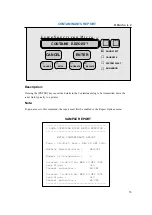
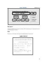
Page 21: ...Fault log to be transmitted down the serial link typically to a printer Note To gain access to this report it must first be enabled in the Report Options menu FAULT REPORT SAMPLE REPORT LOMA SUPERSCAN...

Page 22: ...is actioned Test wand sizes can be entered up to 10 00mm this allows entry of all the standard available Loma test wands An entry must be made to ensure the ferrous test wand is prompted for during a...

Page 23: ...ey and then the and keys to alter the flow length of the product Scope 0 to 999mm Default 250mm Notes Entering a value which is too short will cause the run error LED to flash when product flows indic...

Page 24: ...optimum head power working mode compensation and threshold values for the product used are automatically calculated see the Principles of Operation section for more information about these settings If...

Page 25: ...our nearest LOMA Service Centre POWER REDUCING Indicates that the unit is reducing the head power to account for the product effect of the product HEAD LOCKED Indicates that the unit is using the HEAD...

Page 26: ...TER CANCEL 26 MENUS A to Z Description This menu entry shows the number of packs which have been checked without metal in them since the current batch was started See Batch Reset for more information...

Page 27: ...cycle whereas if locked the HEAD POWER setting will not be altered by a calibration cycle This value should be set to UNLOCK unless a head power setting has been advised by LOMA which must not be alte...

Page 28: ...Head Locking menu must also be set to LOCKED so that the settings cannot be overridden during a calibration cycle Press the ENTER key then the and keys to adjust the head power for the current produc...

Page 29: ...nterval time is set to 01 00 which is equal to an hourly prompt The interval time cannot be set below the Test Window time plus 1 minute Press the ENTER key and then the s and t to set the required ti...

Page 30: ...dopt and should be chosen such that the sensitivity is maximised whilst reducing the false reject rate to an acceptable level Scope Default 100 to maximum threshold 500 Maximum Threshold This sets the...

Page 31: ...Notes This menu will only appear if first enabled in the User Options menu and product I is running In order to make sure that the correct head power is selected for product I carry out a full calibra...

Page 32: ...g the signal level To lock the keyboard press the ENTER key At this menu command To gain access to the password entry to unlock the keyboard press any key Entering the correct code at the password pro...

Page 33: ...YSTEM FAULT RUN ERROR I S C L o m a S u p e r s c a n M i c r o SETUP ENTER CANCEL 33 MENUS A to Z Description The contents of this menu are usually only used by LOMA service personnel Press the ENTER...

Page 34: ...to know the software version that is fitted to your machine and this can be obtained from within this menu The machine ID is set to the serial number of the machine when the unit is dispatched from o...

Page 35: ...r normal operating conditions this menu will be disabled as there is no need to carry out manual adjustment to these settings which are set during the commissioning procedure If this menu is enabled i...

Page 36: ...error message BAD PACK will be displayed and the calibration cycle terminated Press the ENTER key and then the and keys to adjust the maximum threshold setting Scope min thrsh to 49990 Default 15000 2...

Page 37: ...a value about 15 50 higher than the maximum signal levels for the product The larger the amount of product signal variation the higher the minimum threshold will need to be set This will provide a re...

Page 38: ...ll be used in the Results menu to show the current running product and if enabled will be used on reports as well Press the ENTER key to edit the product name Use the and keys to alter the character a...

Reviews: