63
COMPILER TECO/ATL
REG. CODE
1-5302-296
MODEL N°
50510
DATE OF ISSUE
01.89
REVISION
02
ENDORSED
DATE
17.04.2003
168
167
g/kW.H
268÷275
251÷265
238÷251
247÷257
247÷257
265÷279
258÷272
238÷251
258÷272
251÷265
245÷254
245÷254
245÷254
g/CV. h
197÷202
185÷195
175÷185
182÷189
182÷189
200÷209
190÷200
175÷185
190÷200
185÷195
180÷187
180÷187
180÷187
11LD625-3
11LD625-3
11LD625-3
11LD625-3
11LD625-3
11LD535-3
11LD535-3
11LD535-3
11LD626-3
11LD626-3
11LD626-3
11LD626-3
11LD626-3
CV
N 38
NB 35,16
NB 30,60
NB 24
NB 20
N 33,3
NB 29,92
NB 25,84
N 42
NB 39
NB 33
NB 27,3
NB 22
kW
N 27,9
NB 26
NB 22,5
NB 17,65
NB 14,7
N 24,5
NB 22
NB 19
N 31
NB 28,6
NB 24,2
NB 20
NB 16,1
38÷40
43÷46
52÷56
66÷69
79÷82
43÷45
50÷53
62÷66
36÷38
40÷42
48÷51
59÷61
73÷76
3000
3000
2200
1800
1500
3000
3000
2200
3000
3000
2200
1800
1500
XII
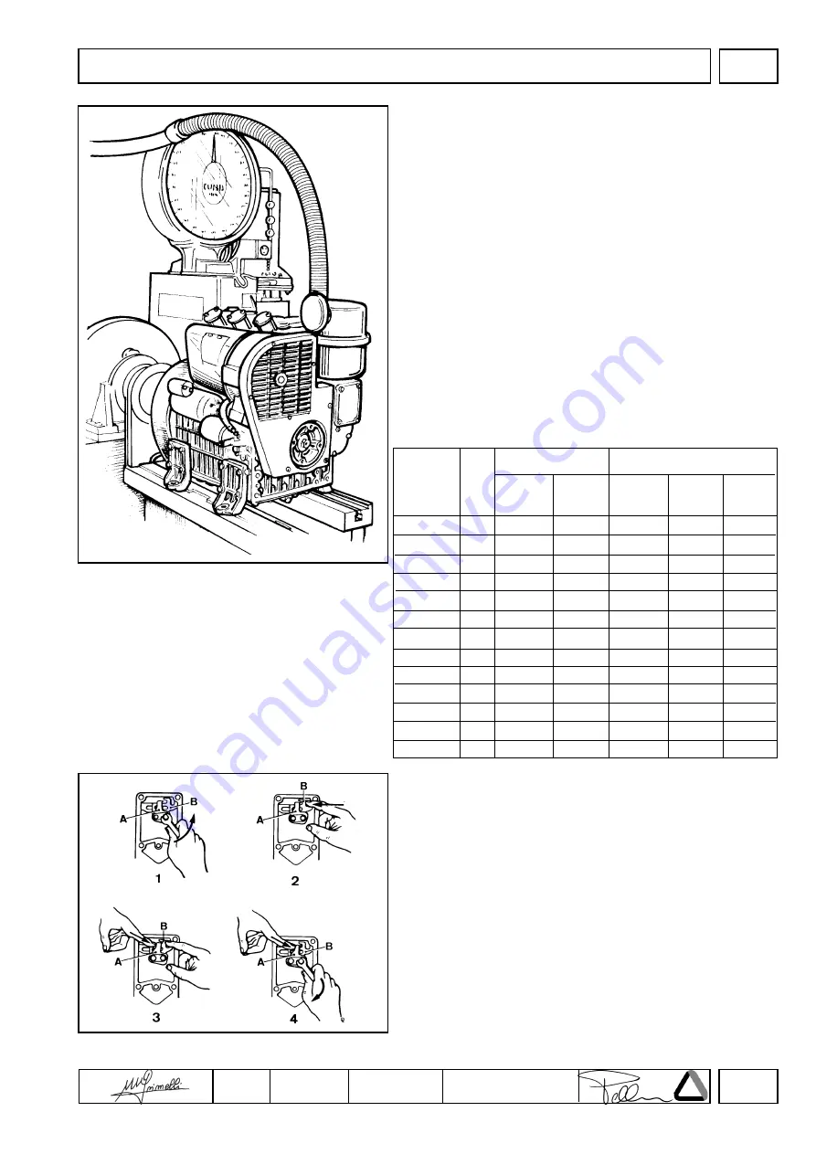
Injection pump delivery setting with engine at the torque
dynamometer
1) Bring engine to idling speed
2) Unscrew delivery limiting device
C
(see page 59)
3) Bring engine to the power and r.p.m. required by the manufacturer
of the device,
4) Check that consumption falls within the table specifications (see
below). lf consumption is not as indicated change balance
conditions at the torque dynamometer by varying the load and
adjusting the governor.
Under stable engine conditions check consumption again.
5) Tighten limiting device
C
until the engine r.p.m. decreases. Lock
the iimiting device by means of lock nut.
In versions with manually-operated mechanical extra fuel feeding
D
perform this operation keeping drive rod
E
as shown in the figure.
6) Release brake completely and check at what speed the engine
becomes stable.
Speed governor should comply with the requirements of the class
indicated by the manufacturer of the device.
7) Stop the engine
8) Check valve clearance when the engine has cooled down.
Required settings (as most commonly applies)
Stop setting
Remove fuel feeding pump and cover.
1) Loosen both bolts fixing plate
A
.
2) Push injection pump
B
control rod to the right and keep it in this
position.
3) Push plate
A
to the right until it touches rod
B
and stop.
4) Release rod
B
and push plate
A
to the right so that rod
B
has a
stroke of 1 mm.
Tighten both bolts.
Note
: Under these conditions no damage can be caused to the
injection pump rack rod stops by sudden impacts due to the
available control solenoids.
SETTINGS
Time (sec.)
for 100 cmc
POWER
Specific fuel consumption
Engine
R.P.M.


