- 23 -
Workshop Manual 12 LD _ cod. 1.5302.460 - 3° ed_ rev. 02
12
13
14
15
16
4
A
0
,
2
4
B
5
,
3
5
C
8
1
0
,
4
1
÷
0
0
0
,
4
1
D
0
6
0
,
4
1
÷
0
5
0
,
4
1
A
0
2
,
1
3
÷
0
8
,
0
3
B
0
2
,
5
2
÷
0
8
,
4
2
A
6
1
0
,
0
4
÷
0
0
0
,
0
4
B
0
4
1
,
0
4
÷
0
2
1
,
0
4
C
6
1
0
,
4
3
÷
0
0
0
,
4
3
D
0
4
1
,
4
3
÷
0
2
1
,
4
3
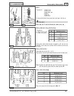
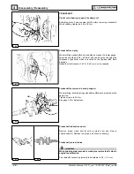
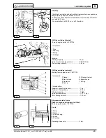
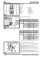
Valves
Components:
1 Intake valve
2 Spring seat
3 Valve stem seal
4 Spring
5 Retainer
6 Half collets
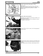
To remove half collets firmly press down as shown in the figure.
Important
Valve stem seal 3 must be fitted to the intake valve only.
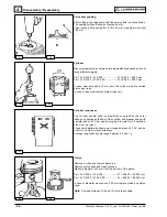
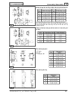
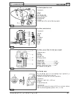
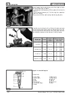
Valve guides and valve guide housings
Components:
1 = Exhaust valve guide
2 = Intake valve guide
Valve guides with outside diameter increased by 0.5 mm are also
available; in such cases valve guide bore C should also be increased
by 0.5mm.
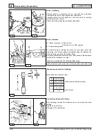
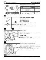
Valve guide insertion
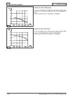
Heat cylinder head up to 160 ÷ 180°C
Press guides considering the A and B distances from the head piane.
Note: If guides are seated with stop ring C, first locate the ring in place
and then position guides without considering A and B.
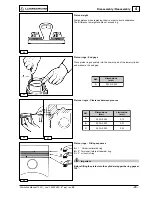
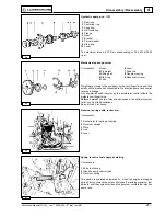
Valve seats and housings
Press valve seats into the housings and cut
α
αα
αα
at 45°.
Ref.
Dimensions (mm)
Ref.
Dimensions (mm)
Ref.
Dimensions (mm)
Disassembly / Reassembly
INTAKE
VALVE
EXHAUST
VALVE


