background image

Section 1    Safety and General Information 


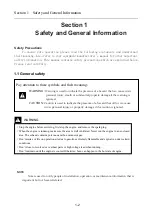
Safety Precautions 

To ensure safe operation please read the following statements and understand 

their meaning. Also refer to your equipment manufacturer's manual for other important 
safety information. This manual contains safety precautions which are explained below. 
Please read carefully. 


1.1 General safety 


WARNING 


NOTE 

Note is used to notify people of installation, operation, or maintenance information that is 

important but not hazard-related.


Pay attention to these symbols and their meaning


WARNING:


Warning is used to indicate the presence of a hazard that 

can 

cause 

severe 

personal injury, death or substantial property damage if the warning is 
ignored.


CAUTION: 

Caution is used to indicate the presence of a hazard that 

will 

or 

can 

cause 

minor 

personal injury or property damage if the caution is ignored.


·

Stop the engine before servicing, first stop the engine, and remove the spark plug. 

·

When the engine is running, make sure the area is well ventilated. Never run the engine in an enclosed 

area. The exhaust contains poisonous carbon monoxide gas. 

·

Don’t smoke or fire on operation site due to gasoline extremely flammable and explosive under certain 

conditions. 

·

Don’t close to revolved or overheat parts or high voltage lead when running. 

·

Don’t maintain until the engine is cooled. Otherwise, burn can happen in the hot state of engine. 


Section 1 

Safety and General Information


1-2 

Summary of Contents for G250D

Page 1: ...SERVICE MANUAL ...

Page 2: ...afety and General Information 1 Specification 2 Maintenance 3 Disassembly and service 4 ALL INFORMATION ILLUSTRATIONS DIRECTIONS AND SPECIFICATION INCLUDED IN THIS PUBLICATION ARE BASED ON THE LATEST PRODUCT INFORMATION AVAILABLE AT THE TIME OF APPROVAL FOR PRINTING LONCIN GENERAL PURPOSE ENGINE CO LTD RESERVES THE RIGHT TO MAKE CHANGES AT ANY TIME WITHOUT IN CURRING ANY OBLIGATION WHATEVER NO PAR...

Page 3: ...nd General Information 1 1 General safety 1 2 1 2 Service rules 1 3 1 3 Serial number location 1 4 1 4 Oil Recommendations 1 5 1 5 Torque values AND Other Detail Specs 1 5 1 6 Maintenance standards 1 7 1 7 Troubleshooting 1 8 1 8 Special tool 1 11 1 1 1 ...

Page 4: ...use severe personal injury death or substantial property damage if the warning is ignored CAUTION Caution is used to indicate the presence of a hazard that will or can cause minor personal injury or property damage if the caution is ignored Stop the engine before servicing first stop the engine and remove the spark plug When the engine is running make sure the area is well ventilated Never run the...

Page 5: ... that don t meet design specifications may damage the device or engine 2 Use the special tools designed for this unit 3 Install new paper gaskets O ring when reassembling 4 When screwing bolts or nuts begin with larger diameter inner bolt first and tighten to the specified torque diagonally unless a particular sequence is specified 5 Clean parts in cleaning solvent upon disassembly Lubricate any s...

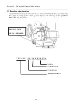
Page 6: ...he crankcase as shown on the following drawing when inquiring about engine or ordering parts in order to get correct parts for the unit being serviced by LONCIN INDUSTRIAL CO Ltd s dealer TXXXXX XX XX XXXXXXX ENGINE TYPE SERIAL NUMBER 1 4 Serial no Production month Production year Development order no ...

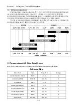
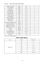
Page 7: ...r class oil The SA oil viscosity and service classification are in the API label on the oil container We recommend that you use API SERVICE Category SE or SF oil 1 5 Torque values AND Other Detail Specs Note For ALL bolts and nuts listed above refer to the table of standard torque values Bolts and Nuts Bolts or Nuts Specs Torque N m Dosage Cylinder Head Cover Bolts M6 16 8 12 4 Cylinder Head Bolt ...

Page 8: ...olts M6 12 8 12 6 Muffler Hex Nuts M8 27 30 2 Fuel Tank Bolt M6 12 8 12 1 Holder Electric Starting Box Bolt M6 20 8 12 1 Engine Cover2 Bolts M6 20 8 12 3 Engine Cover1 Acorn Nut M6 8 12 2 Start Motor Cross Screw M4 55 1 5 3 2 EX Stud M8 34 27 30 2 IN Stud M6 113 8 12 2 Valve Adjusting Bolts M8 26 32 2 Valve Adjusting Nuts M6 8 12 2 Spark Plug F7RTC 27 30 1 Note For ALL Other Detail Specs Other Det...

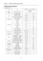
Page 9: ...d inside diameter 18 006 18 017 18 07 big end inside diameter 30 22 30 233 30 274 big end side clearance 0 25 0 65 1 1 crankshaft neck diameter 29 975 29 99 29 915 valve Clearance cold intake 0 10 0 15 Clearance cold exhaust 0 15 0 20 Stem diameter intake 5 468 5 48 5 318 Stem diameter exhaust 5 428 5 44 5 275 Valve guide Inside diameter intake exhaust 5 50 5 512 5 572 Stem to guide clearance inta...

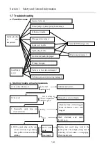
Page 10: ...lter clogged Check carburetor nozzle tube clogged Wash electrode and check throttle open If overflowing check float valve No or weak spark Replace new spark plug recheck the igniting state Check high voltage lead if switching off or broken or creepaging Check igniter coils Good spark Starting trouble at low temperature Incorrect oil make Primer pump or primer pump hose damage Igniter coil trouble ...

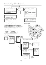
Page 11: ...ck valve gap if correct Check cylinder cover if tightened Check combustion chamber if damaged Check pad valve or valve retainer Check piston ring piston and Check spark igniting state Spark plug gap 0 7 0 8mm Replacing spark plug Switch off the black lead and recheck Engine switch trouble Replacing Poor insulating High voltage broken and creepaging No spark Affirm resistance of the first and secon...

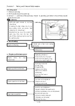
Page 12: ...lug hole Engine starts but stops immediately Spark plug dirt and wet Carburetor fuel level too high Carburetor bolt adjusting wrong Carburetor insulator damaged Engine speed does not increase Spark plug trouble dirt Throttle closed Clogged muffler Improper valve timing Water in the carburetor Overheating Poor valve seat contact Over load Engine speed does not decrease Governor out of adjustment Th...

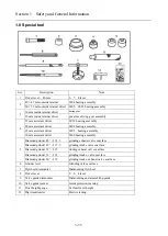
Page 13: ...bearing assembly 30 mm assistant driver 6206 bearing assembly 5 Diamond grinder 45 φ24 5 grinding exhaust valve seat face Diamond grinder 45 φ27 5 grinding intake valve seat face Diamond grinder 32 φ25 rinding exhaust valve seat face Diamond grinder 32 φ28 grinding intake valve seat face Diamond grinder 60 φ30 grinding intake exhaust valve seat face 6 Grinder lever Grinding valve seat face 7 Flywh...

Page 14: ...Section 2 Specifications 2 Specifications 2 1 Parameter 2 2 2 2 Dimensional drawings 2 4 2 3 P T O Dimensional drawings 2 5 2 2 1 ...

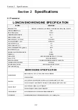
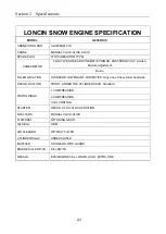
Page 15: ...E 70db A ROTATION ANTI CLOCKWISE from P T O side FUEL TYPE REG UNLEADED IGNITION MODE TRANSISTORIZED MAGNETO IGNITION LUBRICATION SYSTEM SPLASH STARTING SYSTEM RECOIL ELECTRIC START DRY WEIGHT Kg 21 SNOW ENGINE SPECIFICATION GOVERNOR MECHANICAL SET AT NO LOAD 3300 100RPM FIXED SPEED VALVES OHV INTAKE MARTENSITE STEEL 4Cr10Si2Mo GB T1221 1992 OHV EXHAUST AUSTENITIC STEEL 5Cr21Mn9Ni4N GB T1221 1992 ...

Page 16: ...n FILLER LOCATION STANDARD LOW MOUNT W DIPSTICK Only one at the cylinder head side DRAIN LOCATION FRONT UNDER THE CYLINDER HEAD Standard PISTON RINGS 1 COMPRESSION 2 COMPRESSION 3 OIL CONTROL STARTER RECOIL AT 8 O CLOCK POSITION FUEL TANK MANUAL CLICK CLICK FLYWHEEL WITH RING GEAR OIL SEAL OBM AIR CLEANER WITHOUT FILTER CYLINDER Shield ADDED SHIELD MUFFLER STANDARD WITH GUARD ENGINE KILL SWITCH KI...

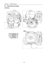
Page 17: ...Section 2 Specifications 2 2 Dimensional drawings G250F D S 2 4 ...

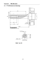
Page 18: ...Section 3 Maintenance 2 3 P T O Dimensional drawings B4轴 Type B4 2 5 ...

Page 19: ...Section 3 Maintenance 3 Maintenance 3 1 Maintenance schedule 3 2 3 2 Engine oil 3 2 3 3 Spark plug 3 4 3 4 Valve clearance 3 5 3 5 Governor 3 6 3 6 Fuel filter 3 7 3 3 1 ...

Page 20: ...ertain applications it may be possible drain the engine oil from the oil filler tube a turn the fuel valve to the OFF position b Remove the oil filler cap dipstick c Tip the engine and allow the oil to drain from the oil filler tube into a suitable container REGULAR SERVICE PERIOD Performed at every indicated month or operating hour interval whichever comes first Each use First month or 20 Hrs Eve...

Page 21: ...filler tube Remove the oil filler cap dipstick and check the oil level on it Bring the level to the upper mark on the dipstick 5 after running the engine recheck the oil level and adjust if necessary Wash your hands thoroughly with soap and water as soon as possible after contact with used oil which contains carcinogenic substances Please dispose of used motor oil and the oil containers in a manne...

Page 22: ... deposits Replace the spark plug if you have any doubts about its condition 4 Measure the electrode gap with a wire gap gauge Adjust the gap to 0 7 0 8mm by carefully bending the ground electrode 5 use a spark plug wrench to tighten the plug enough to compress the washer For a used plug tighten 1 8 to 1 4 of a turn after the spark plug seats For a new plug tighten 1 2 turn after the spark plug sea...

Page 23: ...1 Measure the clearance between the rocker arm and the valve stem with a feeler gauge Intake 0 10 0 15 mm Exhaust 0 15 0 20mm To adjust valve clearance hold the rocker arm pivot and loosen the pivot lock nut 2 Turn the rocker arm pivot to obtain the specified clearance 3 Hold the rocker arm pivot and tighten the pivot lock nut 4 Recheck the clearance and readjust if necessary 5 Install the cylinde...

Page 24: ...ull open tighten the nut 3 Check governor arm and throttle if moving freely 4 Start engine and allow it to warm up to the normal operating temperature Move lever to make engine at maximum speed Adjust throttle lever screw to make the throttle lever not to exceed this position let speed out maximum speed 3 6 Quadrate head bolt Limit screw Governor Arm Governor Rod Governor Spring Throttle return sp...

Page 25: ...g 1 Drain the fuel in the fuel tank thoroughly out and remove the fuel tank 2 Remove the fuel tube and remove filter from the fuel tank 3 Wash the filter with solvent and check strainer if there is damaged put the O ring on the filter reassemble the filter and tighten to specified 2 N m After that check if there is leaking Fuel cap Outlet fuel Fuel tank Fuel tube 3 7 ...

Page 26: ... 4 3 4 3 Fuel tank 4 4 4 4 Muffler 4 5 4 5 Air Cleaner 4 6 4 6 Carburetor 4 7 4 7 Engine cover 1 4 10 4 8 Governor bracket and throttle control assy 4 11 4 9 Recoil starter 4 12 4 10 Flywheel ignition coil 4 15 4 11 Cylinder head valves 4 18 4 12 Crankshaft piston camshaft 4 24 4 13 Governor 4 31 4 4 1 ...

Page 27: ...Section 4 Disassembly and service 4 1 DRAIN BOLT Disassembly Reassembly Section 4 Disassembly and service 4 2 4 1 FLAT WASHERφ10 16 1 5 3 BOLT M10 1 25 15 2 TORQUE 22 25N m OIL EXTENSION ROD ...

Page 28: ...Section 4 Disassembly and service 4 2 CONTROL BOX BRACKET Disassembly Reassembly SCREW BOLT M4 55 2 BOLTt M6 20 TORQUE 8 12 N m ELCETRIC STARTING BOX HOLDER 4 3 FLAT WASHER 2 ...

Page 29: ...may ignite 4 4 Bolt M6 20 3 Torque 8 12 N m Fuel tank cap Assembly Make sure the vent hole is clean and unclogged Blow if necessary Fuel tank Fuel tank capability 3 0L Assembly Clean dirt ants thoroughly before assembling Outlet nozzle fuel tank Bolt M6 12 Torque 8 12 N m CLIP Engine cover Assembly Check to be sure the strainer is clean and undamaged before installation Fuel Strainer ...

Page 30: ... 4 Muffler Disassembly Reassembly 4 5 Protector Muffler Bolt M6 12 Torque 8 12 N m Muffler Pad Plate Nuts M8 2 Torque 27 30 N m Assembling Lightly tap with plastic hammer to remove dirt then assemble Body Muffler Muffler protect bracket ...

Page 31: ...e 4 5 Air cleaner Disassembly Reassembly 4 6 Nuts M6 2 Torque 8 12 N m Key Switch Stop Switch Engine Stop Air Heat Box Disassembly assembly When disassembling and assembling choke will turn and fuel valve switch off Air Box Seat CLIP ...

Page 32: ...when assembling Insulating pad Disassembly disassemble reset spring pull the carburetor out when throttle notch aligns on line with lever and pull the governor lever off Carburetor Insulator Gasket Carburetor Gasket Throttle Reset spring Governor lever Notch Air Cleaner Elbow Gasket Assembling Reassemble after checking for no broken and pay attention to direction 4 7 Fuel tube Assembly Check for n...

Page 33: ...ssed air before assembling Main jet Clean thoroughly with compressed air before assembling Float Check for smooth movement after assembling Assembling bolt Check for fuel leaking after assembling Drain bolt Float valve Assembly Assemble after checking for float seat float valve and float valve spring wearing float valve seat REPLACE Air pump Primer Primer Line Clip 2 Float Pin float valve Spring N...

Page 34: ... hole Note The carburetor has inner through and outer through air holes For outer through hole it passes through to carburetor oil cup as well as inner through air hole is closed For inner through hole it passes through to carburetor oil cup as well as outer through air hole is closed Standard height 13 7 mm In order to avoid injury please wear safety eyeglasses or other eye protector when using c...

Page 35: ...ice 4 7 Engine cover Disassembly Reassembly 4 10 Nut M6 Torque 8 12 N m Engine cover Fuel tube Assembly Check for no crack or aged before assembling if necessary please replace Knob Fuel Swtich Screw M4 18 Safeguard tube Fuel Swtich ...

Page 36: ...y Disassembly Reassembly 4 11 Assembly Insert long end of hook onto lever Throttle reset spring Assembly Put long end of hook onto control lever Governor spring Nuts M6 Bolt Quadrate Head Governor Arm Governor Rod Bolt M6 8 2 Torque 8 12 N m SHROUD COMP CONTROL ASSY Engine switch ...

Page 37: ...n t let the spring out when disassembling Bolt M6 8 Torque 8 12 N m Recoil starter Reassembly Remove dirt and debris before installation The installation direction can be changed by changing the relative positions of the holes in recoil starter case Cover comp fan Bolt Support Double Bolt M6 12 Torque 8 12 N m 4 12 CLIP ...

Page 38: ... onto the reel in the arrowed direction and remain about 30cm outside the starter wheel Note Make sure remaining about 30cm rope outside the starter wheel Assemble the starter wheel on the starter reel insert the hook on the inner side of scroll spring on the convex position of starter dray Grasp the starter grip and pre turn starter wheel two turns as shown as arrow direction Wear gloves and eye ...

Page 39: ... as drawing WARNING Don t allow the starter wheel leaving off the starter tray otherwise the spring fly out to injure person Assemble the pawl and friction spring together on the starter wheel tighten the bolt of bolt Pull the starter rope several times to make sure if the pawl moves correctly 4 14 ...

Page 40: ...y After assembling check to be sure that the woodruff key is still in its slot on the crankshaft High tension cord Spark plug Igniting coil Caution When servicing take care not to damage the fan blades Reassembly Assemble the fan aligning the four lugs on the back of the fan with the small holes in the flywheel Cooling fan Assemble aligning the lugs on the starting cup with the small holes in the ...

Page 41: ... 35 0 45 mm Notice Adjust both ends of the coil to the same gap Avoid the magnet portion of the flywheel when adjusting Inspection Igniting coil Primary coil Put the tester terminal and lead terminal to contact with iron core of coil and measure the primary coil resistance Secondary coil Put the tester terminal and removed spark plug cap s high tension cord to contact with iron cord and measure th...

Page 42: ...ment is required only when the ignition coil or the flywheel has been removed 1 Loosen the ignition coil mounting bolts 2 Insert the thickness gauge or a piece of paper of the proper thickness between the ignition coil and the flywheel both gaps should be adjusted simultaneously Avoid the magnet when adjusting the air gap 3 Push the ignition coil firmly toward the flywheel and tighten the mounting...

Page 43: ...l Installation Loosen and tighten the bolts in a crisscross pattern in 2 3 steps Remove carbon deposits from the combustion chamber and check the valve seat before assembling Measure the cylinder pressure after assembling Cylinder pad Pin 2 4 18 Bolt M10 65 4 Cylinder head Tube Breather Gasket Cap Breather Cap Breather Chamber Filter Head Cover Bolt M5 10 2 Torque 8 14 N m HOSE ...

Page 44: ...Caution don t disassemble the valve spring while the cylinder cover is not removed or the valve stem will drop into the combustion chamber Valve rotator 2 Be sure to assemble If the engine is operated with the rotator not attached the valve will drop into cylinder Cylinder head Push rod 2 Assembly Check the two ends of the push rod for wearing and push rod for straightening Be sure that two ends o...

Page 45: ...bustion chamber Clean off any gasket material from the cylinder head surface Check the spark plug hole and valve areas for cracks Check the cylinder head for warpage with a straight edge and a feeler gauge as shown Service limit 0 10 mm Valve stem OD Inspect each valve for face irregularities bending or abnormal stem wear Replace the valve if necessary Measure and record each valve stem OD Standar...

Page 46: ...If the intake valve guide is worn beyond the service limit Replace the cylinder head 1 chill the replacement exhaust valve guide in the freezer section of a refrigerator for about an hour 2 use a hot plate or oven to heat the cylinder head evenly to 150 330 Check the temperature with a temperature indicating stick available at welding supply stores or equivalent Wear heavy gloves to prevent burns ...

Page 47: ...ve been bent during installation Replace the valve guide if it is bent or damaged 6 check the valve stem to guide clearance valve seat reconditioning 1 thoroughly clean the combustion chambers and valve seats to remove carbon deposits 2 apply a light coat of Prussian Blue or erasable felt tipped marker ink to the valve faces 3 insert the valve and then lift them and snap them closed against their ...

Page 48: ...or even valve seating 3 apply a light coat of Prussian Blue or erasable felt tipped marker ink to the valve faces 4 insert the valves and then lift them and snap them closed against their seats several times Be sure the valve does not rotate on the seat The seating surfacing as shown by the transferred marking compound should have good contact all the way around Notice To avoid severe engine damag...

Page 49: ...lush to check Making sign Oil filler cap Crankcase cover Timing gear Crankshaft Assembly Insert until the bearing contacts crankshaft be careful not to damage oil sealing Connecting rod cover Assembly Face the sprinkling oil spoon to cam and align the connecting rod to convex portion of the cover in assembling Connecting rod bolt 2 Crankcase Governor driving gear Oil sealing 28 41 25 6 mm Crankcas...

Page 50: ... part to the governor drive gear and remove the crankshaft and timing gear by manual compressor Disassemble the governor drive gear in the same way Assembly Timing gear Using the old gear for reference make a mark at the same position on the new gear Using a hydraulic press lever and inner retainer assembler the special tools shown press the timing gear onto the crankshaft after aligning old and n...

Page 51: ... piston to piston pin hole with 120 degree First ring Second Ring Oil Rings Attention Piston Rotation Arrow should point at Valve Lifter Attention First and Second Rings are stagger 150 210 Attention Scrape Rings are stagger 150 210 from the oil Ring Oil Splash Spoon Connecting Rod Piston Pin Clip 2 Piston Rotation Arrow Piston Pin Assembly Put the one end into the piston slot clamp other end by s...

Page 52: ... crankshaft deeply Otherwise oil may seep through the oil seal Inspection Piston pin OD Model Standard Service limit G250F D S 18 0 mm 17 954 mm Cylinder inside diameter Measure three points on the X and Y shaft and record cylinder inside diameter X shaft is vertical to crankshaft and Y shaft parallel to crankshaft Take maximum reading as the wearing and tapering of the cylinder Model Standard Ser...

Page 53: ...e limit Top 1 0mm 0 87 mm Second 1 2mm 1 07 mm Piston ring end gap Parts Standard Service limit Top 0 2 0 4 mm 1 0 mm second 0 3 0 5 mm 1 0 mm Oil 0 2 0 7 mm 1 0 mm Before measuring end gap use the piston top to position the ring so it will not be cocked in the cylinder bore Piston pin hole ID Model Standard Service limit G250F D S 18 002mm 18 048 mm Piston pin to Piston hole gap Standard Service ...

Page 54: ...kshaft pin OD Standard Service limit 29 975 29 99 mm 29 915 Connecting rod big end axial clearance Standard Service limit 0 25 0 65 mm 1 1 mm Connecting rod big end oil clearance Radial 1 Clean all oil from the crankshaft neck journal and inside side 2 Place a piece of plastic gauge on the crankshaft neck journal assemble connecting rod and tighten the bolts to specified torque Bolt torque 14 N m ...

Page 55: ... use a connecting rod lower than standard value Camshaft cam height Standard Service limit IN 28 52 mm Replace under 28 27 mm EX 28 56 mm Replace under 28 31 mm Camshaft OD Standard Service limit 13 966 13 984 mm 13 916 mm Note the location of the decompressor mechanism check to be sure it moves freely Camshaft axletree ID Standard Service limit 14 0 14 018 mm 14 048 mm Standard Service limit 0 04...

Page 56: ...heck flyweight for freely turning Clip Assembly Firmly snap in the slot of the shaft Governor slider Separate the governor flyweight and fix in then check for smoothly moving Washer Assembly Assemble in the case Split pin Assembly Immediately fit the split pin after assembling governor arm and move the governor arm to against the governor slider Insert the straight side of the split pin into the s...

Page 57: ...CO Ltd Add No 99 Hualong Road Jiulongpo District Chongqing China Tel 86 23 8906 7577 7599 Fax 86 23 8906 7533 隆鑫通用动力股份有限公司 地址 重庆市九龙坡区华龙大道 99 号 电话 86 23 8906 7577 7599 传真 86 23 8906 7533 Web site www loncinengine com E Mail marketing loncinengine com ...

Reviews: