background image


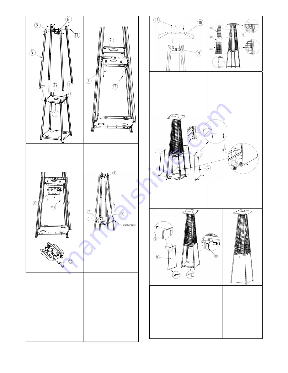
Connect 4 upper supports (5) 

to the lower supports (4) and 

fixed by screws (17), then fix 

the upper plate (6) to 4 upper 

supports (5) by screws (17). 

Fix the plate cover (7) onto 

the middle plate (1) by the 

screws (17). 


Install AA battery (20) into the 

control box, then, fix the 

control box (2)underneath the 

middle plate (1) by screws 

(17) 

Note: the control know must 

face to the side where the 

magnet is installed in the 

middle plate. 

Carefully put the glass tube 

(8) up through the centre 

hole in the upper plate (6), 

make sure the rubber ring is 

attached on the lower end of 

the glass tube (8). Move 

and site the glass tube (8) 

through the hole of the plate 

cover (7) on the middle 

plate (1), check and ensure 

that the glass tube (8) 

covers the centre hole of the 

middle plate (1). 


Fix the reflector (10) onto the 

damper (9) by screws (17). 

Attach the protection guards 

(11), (13) onto the upper 

frame by putting its hooks 

into the holes of the frame. 

Connect two guards with the 

connecting tube (12), fix the 

guards with the fixing 

brackets (14). 


Fix 3 side panels (1%) by the 

screw (17). 

Note: do not cover the side 

where the control know is 

situated 

If the wheel kit is supplied, 

fix it at the back of the base 

shown. 


Screw the knob (18) onto the front 

panel (16), attach the panel by 

inserting its two hooks into the holes 

on the bottom plate (3), hook the 

chain (19) to the hole in control box 

then close the panel to the middle 

plate, the panel is attracted by the 

magnets. 

Tip: tge chain can hold the panel by 

operating the controls 

Completed 


Summary of Contents for pyramid flame

Page 1: ...s are stored Prior to use check for damaged parts such as hoses regulators pilot or burner Do not move the heater when in operation Shut off the valve at the gas cylinder before moving the appliance D...

Page 2: ...e heater If excessive abrasion or wear is evident or the hose is cut it must be replaced prior to operating the heater The replacement hose assembly may be obtained from the manufacturer DO NOT use an...

Page 3: ...ss tube 1 9 Damper 1 Preassemb led in upper plate 10 Reflector 1 11 Lower protection guard 4 12 Connecti ng tube 8 13 Upper protection guard 4 14 Fixing bracket 4 15 Side panel 3 16 Front panel 1 A ch...

Page 4: ...the middle plate 1 check and ensure that the glass tube 8 covers the centre hole of the middle plate 1 Fix the reflector 10 onto the damper 9 by screws 17 Attach the protection guards 11 13 onto the...

Page 5: ...nels it is recommended the belts provided are set up as follows WARNING When the gas bottle is properly tied in by the belts and the heater is moved the gas bottle might still damage the panels if the...

Page 6: ...for use Clean burner holes by using a heavy duty pipe cleaner Compressed air may help clear away smaller particles Carbon deposits may create a fire hazard Clean reflector and glass tube with soapy wa...

Page 7: ...faulty Replace thermocouple Pilot light assembly out of alignment or not in correct location Place pilot light in correct position and retry Any modifications or repairs to the patio heater must be ca...

Reviews: