MigWeld 140 140 AMP MIG Welder
Page
24
of
27
Welding Process
1.
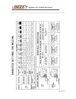
Please refer to the welding manual when selecting welding wires and protective gases
based on the metal thickness.
2.
Please refer to “Welding Control Guide” that is located inside the welding machine door
for the output voltage and wire feed rates.
3.
Inspect output polarity according to the welding wire being used and ensure whether or
not shielding gases are needed.
4.
Connect the ground (work) clamp to the piece(s) to be welded; there should be a good
connection for the ground (work) clamp to the piece(s).
5.
The welding gun should have free movement in the area of the piece(s) to be welded.
6.
Power on the MigWeld140 Welding Machine
7.
Pull down welding protective helmet, press the trigger of the welding gun and begin to
weld. Keep the contact tip of the welding gun at around 3/8” to 1/2” (10-13mm) away
from piece(s) to be welded.
8.
Release trigger of the welding gun and the welding is stopped.
9.
After welding, turn off valve of the compressed gas cylinder (if gas is used) and then
press trigger of the welding gun to release compressed gas in system. Finally, power off
the MigWeld140 Welding Machine.
Optional Spool Gun - Contact your local LONGEVITY dealer for correct Spool Gun
part number.
Your MigWeld140 has a factory installed option to allow you to install and operate a hand
held spool gun. This will allow you to do welding of both Aluminum and Steel. To install the
spool gun you must first power down the welder, remove the standard MIG gun and install
the Spool Gun using the same installation process as described on page 9. You must move
the Change Switch (7) from MIG to Spool Gun. This will disable the drive system of the
welder and enable the Spool Gun’s drive system. Reference the owner’s manual of the Spool
Gun for operating procedures and instructions of the Spool Gun.


