
CDM816D WHEEL LOADER
43
reduction of gear shifts substantially reduce the driver’s labor intensity and increase the comfort.
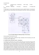
(ii) Working principle:
The torque converter comprises pump pulley, turbine and guide wheel. The working chamber is filled
with working oil. The pump pulley is used to transform the mechanical energy from engine into the
kinetic energy of liquid. It is driven by the engine and rotates at the engine speed to force the oil in
working chamber to impact the turbine with high pressure at a high speed. The turbine absorbs and
transforms the kinetic energy into mechanical energy. The guide wheel (9) is fixed, due to which when
the liquid flow strikes the guide wheel (9) blade and imposes a torque on it, the guide wheel will
produce an equal and opposite counter torque and transmit it back to the turbine via fluid to change its
output torque. The blades of four components have their specific shapes and inlet/outlet angles so that
the liquid can flow in/outflow from the specified channels and directions. However, as the pump pulley
speed changes under the control of throttle and the turbine speed changes with the rotation speed
change imposed by the external load (feedback through axle and transmission) on the output shaft
(e.g. the wheels have no movement in case of starting or braking), the speed, pressure and relative
angle of attach with which the liquid flows into each component are subject to frequent and quick
change and the torque from the pump pulley and the torque reflected by guide wheel also change.
When the torque that the turbine receives from the pump pulley via fluid is forward, the turbine output
torque increases; otherwise, it reduces. The presence of fixed guide wheel makes the torque
conversion of torque converter possible.
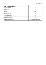
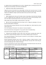
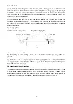
(iii) The inlet pressure of torque converter is 0.50-0.60 MPa and the lubricating oil pressure is
0.20-0.30 MPa. They have been adjusted well at machine delivery and need no adjustment.
(iv) The structure and transmission principle are specified in Transmission part.
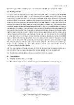
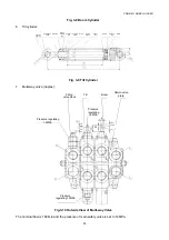
III. Transmission
(i) Structure and transmission principle
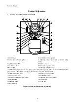
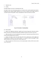
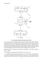
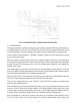
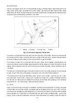
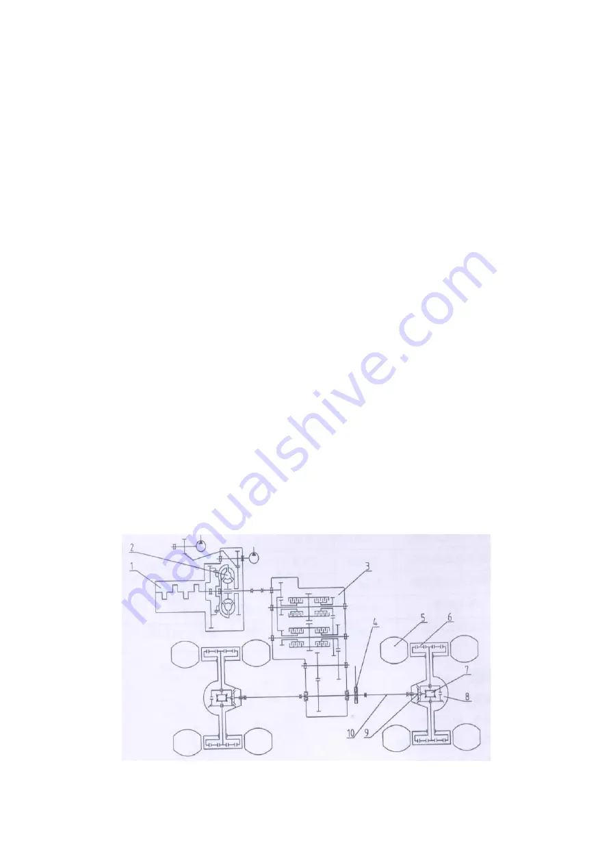
The transmission, torque converter and diesel engine are assembled into a whole (see Fig. 3-1).
Fig. 3-1 Schematic Diagram of Drive System


