Operation Manual
50
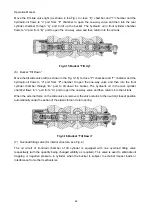
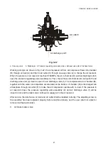
groove, then to the distributing groove of the valve core, to the load ring groove of the valve sleeve and
finally to the load port of the valve body. It is connected with pilot valve through pipeline to get ready to
transmit the steering pressure signal. In this case, no pressure oil from the steering gear flows into the
stator and rotor. Most oil from the pump flows to other working device and then returns to the oil tank
through the EF port of the pilot valve.
When the steering gear turns left or right, the thermal balance port is closed and the load port
produces a pressure signal to transmit it to the pilot valve. At this time, the pilot valve core begins to
move and the CF port expands to supply oil to the steering gear according to the speed of the steering
wheel during steering.
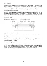
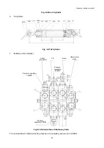
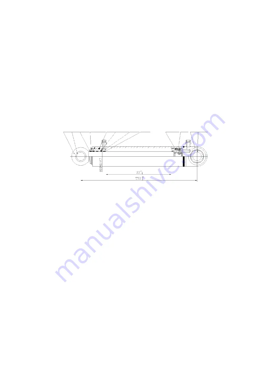
(3) Steering cylinder
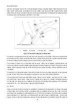
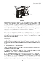
Structure view of steering cylinder
Fig. 3-6 Steering Cylinder
(iii) Maintenance of steering system
(1) The working oil in the steering system shall be kept clean and changed every half a year
generally.
(2) Overhaul or clean the components (such as steering gear, pilot valve, steering cylinder) for the
steering system after working for six months to one year. When disassembling, be careful to protect
the parts from bumps or damages.
VI. Implementhydraulic system
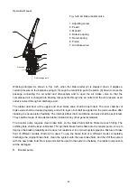
The working device hydraulic system is used to control the movements of the boom and bucket, so as
to meet various operation requirements. It mainly composed of gear pump that’s shared between
working device hydraulic system and steering system, multi-way change valve, boom cylinder, tilt
cylinder, oil suction/return filter, oil tank etc. The working principle is shown in the Fig. 3-7.
Piston rod
Shaft
sleeve
Dust
ring
Circlip for shaft O-ring
Ladder ring
for shaft
Guide
sleeve
Support
ring
Hole square
ring
Piston Cylinder
block
knuckle
bearing

