
Operation Manual
54
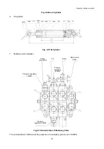
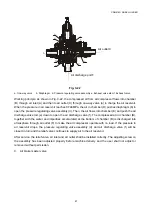
The A1 port of tilt valve is provided with an overload valve and its pressure is set to 12MPa; the B1 port
is equipped with an overload filling valve and the overload pressure is set to16MPa;
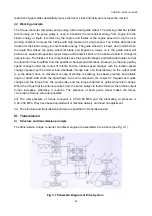
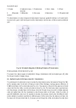
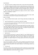
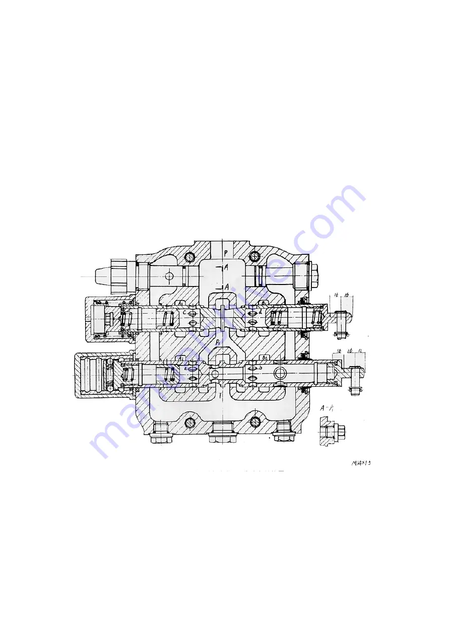
The schematic diagram of interior structure is as follows:
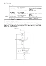
The oil circuit controlled by this valve is designed with a series structure and is used to control the
movement direction of tilt cylinder and boom cylinder by changing the oil flow direction to keep each
part at a fixed position, thus meeting various operation requirements for engineering machinery.
The tilt change valve is 3-position 6-way valve. It can control the up tilting, back tilting and closing of
the bucket.
The boom change valve is a 4-position 6-way valve. It can control the lifting, closing, lowering and
floating of the boom.
The safety valve is used to control system pressure. When the system pressure exceeds the rated
pressure, the valve is opened and the pressure oil returns to the oil tank to protect the hydraulic
system against damage due to high pressure.
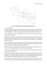
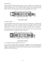
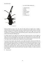
Fig. 3-11 Interior Structure of Multi-way Valve
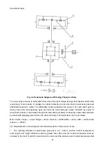
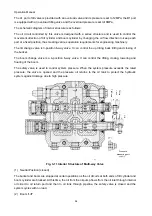
(1) Neutral Position (closed)
The bucket and boom are stopped at certain positions as the oil circuits at both ends of tilt cylinder and
boom cylinder are blocked. At this time, the oil from the oil pump flows from the oil inlet through internal
oil circuit to oil return port and then to oil tank through pipeline, the safety valve is closed and the
system cycles with no load.
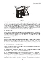
(2) Boom “Lift”
T
ilt
Do
wn
Clo
se
T
ilt
Up
Flo
a
t
Lo
w
e
r
Clo
se
Lift
Pressure
measuring port


