background image

CDM816D WHEEL LOADER

55

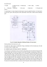
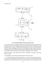
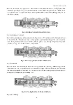
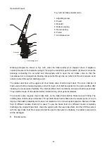
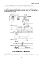
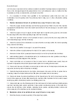
Move the boom slide valve right to close “T” chamber and the hydraulic oil flows to “a” port from “P1”
chamber to open the one-way valve and then into the lower chamber through “A

2

” port to lift the boom.

The hydraulic oil in the upper chamber of boom cylinder returns to the oil tank through “B

2

” port, “b”

port and “T” chamber.

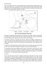
Fig. 3-12 Lifting Position for Boom Slide Valve

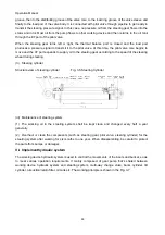
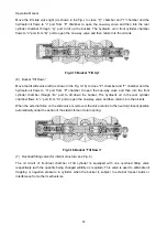
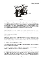
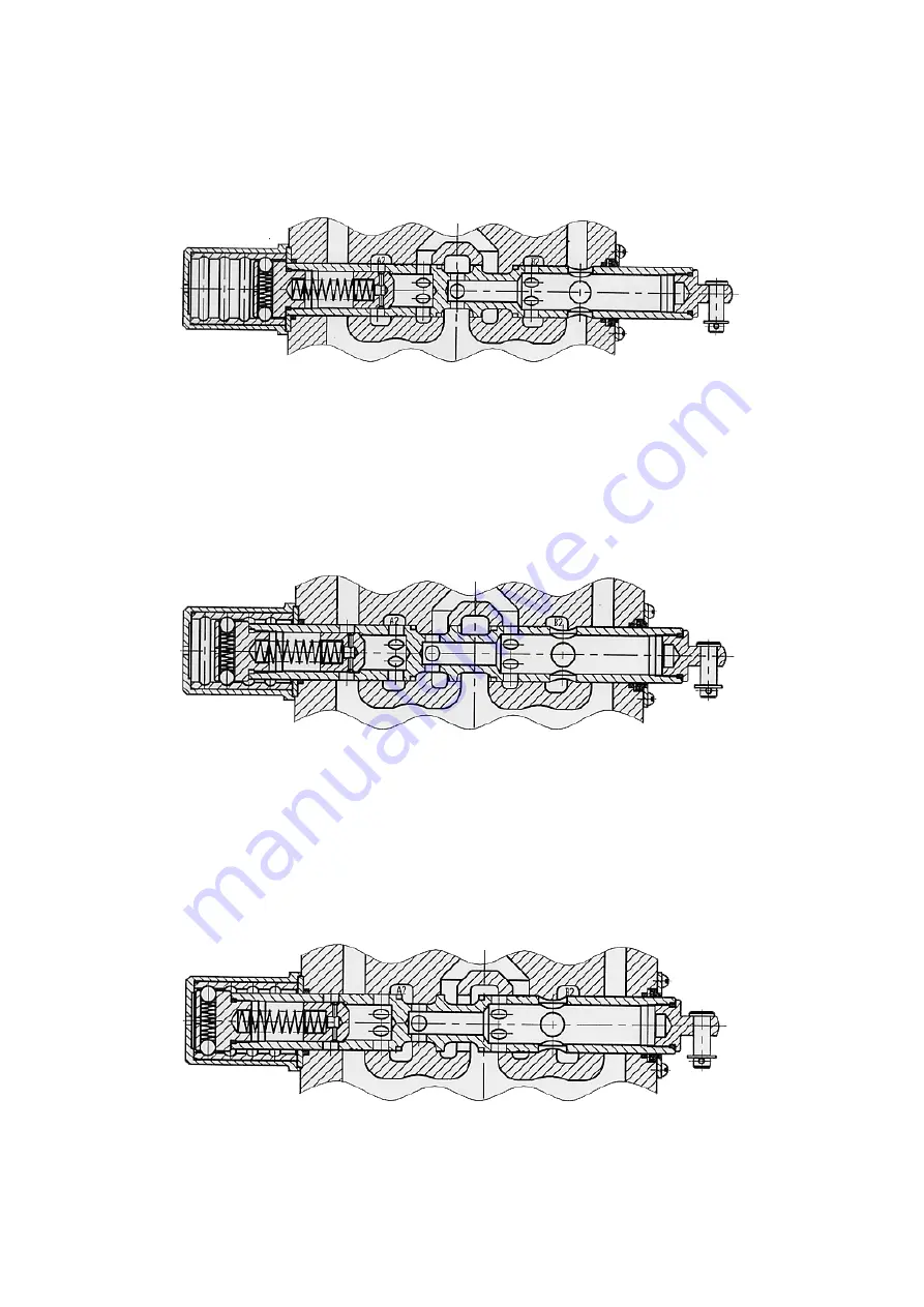
(3) Boom slide valve “Lower”

Move the boom slide valve left (as shown in the Fig.) to close “T” chamber and the hydraulic oil flows
to “b” port from “P

1

” chamber and then into the cylinder upper chamber through “B

2

” port to lower the

boom. The hydraulic oil in the lower chamber of boom cylinder flows through “A

2

” port and “a” port to

open the one-way valve and then returns to the oil tank.

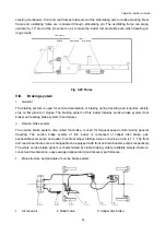
Fig. 3-13 Lowering Position for Boom Slide Valve
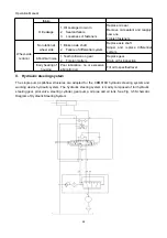
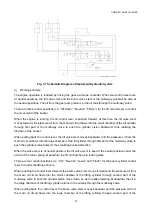
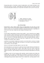
(4) Boom “Float”

Move the boom slide valve left (as shown in the Fig..). At this time, both “A

2

” port and “B

2

” port are

connected to “b” port, “T” chamber and “P

1

” chamber, the upper and lower chambers are connected

and under low pressure. In this case, the cylinder can make the free floating state under the action of
working device weight and ground acting force.

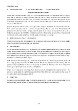
Fig. 3-14 Floating Position for Boom Slide Valve

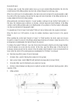
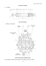
(5) Bucket “Tilt Up”

Summary of Contents for CDM816D

Page 1: ...ntee a safe and efficient operation thus benefitting you a lot Therefore please read and comprehend the safety instructions before operation and strictly follow the relevant instructions and requireme...

Page 2: ...loader loaderfixing in transportation Chapter V common malfunctions and troubleshooting Chapter VI and reference table for densities of common materials Safety This part lists a series of basic safety...

Page 3: ...f wheel loader 21 IV Lubrication 29 Chapter IV Structures of Main Components 31 I Diesel engine 31 II Hydraulic torque converter 31 III Transmission 32 IV Drive axle 34 V Hydraulic steering system 37...

Page 4: ...ing labels which are described in this Manual in detail If you fails to pay due attention to them each operation step will possibly lead to irretrievable damage to yourself or others Each kind of poss...

Page 5: ...vant safety instructions failure to pay sufficient attention to those instructions may cause injuries or even death to yourself or others the relevant safety instructions can be referenced in the foll...

Page 6: ...brake locking insufficient braking force or brake failure thus causing machine non operation and even safety accidents 1 1 8 If the brake plate of the caliper brake has been worn for 2 3 replace it wi...

Page 7: ...re operation 1 2 2 Ensure that all safety labels are clear and legible 1 2 3 Clean or replace the illegible safety labels 1 2 4 Replace the label with illegible icon 1 2 5 To clean the safety labels u...

Page 8: ...t near the specific hazard areas For the conventional safety protections see Caution labels 1 3 5 Some safety labels include the words not mentioned above after the safety warning marks have been used...

Page 9: ...tside the main plate of front frame of loader Risk of crushing Do not stand here when the vehicle makes turning Otherwise injury or death may be caused due to crushing Always lock the bogies of front...

Page 10: ...direction of overall unit Refill with the hydraulic oil in time to avoid loader stop incorrect oil filling may disenable or even damage the machine Fig 3 3 Label for user warning 4 Label location left...

Page 11: ...bels of lifting 6 Label location near the lifting eyes of front and rear frames For loader lifting hang the hook into the lifting eye on the body and adjust the length of the lifting ropes before the...

Page 12: ...7 Label location both sides of rear engine hood Do not have your hands approach to the fan when the engine is running otherwise serious injury or death may be caused Fig 3 7 Warning label of battery w...

Page 13: ...nit Always operate the machine as per the label otherwise machine damage or personal injuries may be caused Fig 3 9 Fuel label 10 Label location near the round dipstick of right fuel tank in the forwa...

Page 14: ...e to avoid engine stop incorrect oil filling may disenable and even damage the machine Fig 3 10 Label of regular check and maintenance requirements 11 Label location on window at the right side of cab...

Page 15: ...Adjustment Replacement Daily 50h 100h 300h 600h 1200h 2400h 1 Check the volume of cooling water or clean the water tank 2 Check the oil pan and oil level of regulator injection pump 3 Check the belt f...

Page 16: ...ting grease at points such asdrive shaft and fan shaft 30 Check the hydraulic oil level and refill if necessary 31 Replace the hydraulic oil filter element clean the tank and change the oil 32 Check t...

Page 17: ...as not to cause economic loss or personnel injury 1 5 3 2 Check if the fixing levers for locking of front and rear frames are at the unlock position 1 5 3 3 Check if each instrument is working normall...

Page 18: ...ll lead to high speed ejection of the hydraulic oil or pipe plug etc 1 5 6 2 Prior to the release of pressure it is prohibited to remove any hydraulic part otherwise personnel injury may be caused 1 5...

Page 19: ...jury and property loss 1 5 9 3 Clear the flammable materials attached on the surface of machine and avoid any inflammable accumulation 1 5 9 4 Do not operate the machine near the open flame 1 5 9 5 Do...

Page 20: ...eating on the rim parts outside spark or excessive brake 1 5 11 2 Tyre explosion is more lethal than the rupture Its explosive power may cast the tyres rim parts and axle parts from the machine for 50...

Page 21: ...or one foot and both hands 1 5 14 3 Do not board or come down from a moving machine and never jump down from the machine Do not get on or off the machine carrying the tools or items Pull the equipmen...

Page 22: ...w the maximum size of the machine 1 5 17 Shutdown of engine 1 5 17 1 After the engine is working under the load do not immediately stop the engine which may cause the overheating and accelerated wear...

Page 23: ...achine s operations will be affected on rainy snowy and foggy days and operation safety should be paid full attention to 1 5 21 2 In case of low visibility clearance lamp and illuminating lamp must be...

Page 24: ...r with low temperature coolant to prevent engine cylinder head and jacket pipe from cracking due to temperature jump 1 5 23 5 For the cooler with an expansion chamber in the process of filling the coo...

Page 25: ...ggles 3 If electrolyte spills on cloth or skin wash it immediately with plenty of water 4 The electrolyte can cause blindness and if it splashes into your eyes immediately wash them with plenty of wat...

Page 26: ...shall not be charged Replace the battery after identifying causes 2 If the terminal post is broken the battery shall not be charged replace the battery after identifying causes 3 The battery with whi...

Page 27: ...ific gravity of the sulfuric acid of the battery will increase and the charging current of the battery will recover gradually 7 If acid is sprayed out of the vent hole when charging stop the charging...

Page 28: ...t is a widely used and generally used construction machinery which can undertake traction leveling and piling etc II Overallperformance parameters 1 Rated bucket capacity m 0 95 2 Rated load t 1 6 3 B...

Page 29: ...er kW speed rpm 55 2400 Max torque N m speed rpm 235 1680 Fuel consumption at rated condition g KW h 251 6 Fuel 0 or 10 light diesel oil OD of exhaust fan mm 490 3 Air compressor Rated speed rpm 1000...

Page 30: ...rd gear I 2 47 Forward gear II 0 88 Reverse gear I 2 52 Reverse gear II 0 898 Working oil pressure Mpa 1 2 1 5 Lubricating oil pressure Mpa 0 2 0 3 Transmission oil pump Model CBG1025 Speed rpm 2400 F...

Page 31: ...e disc diameter mm 210 Brake pad dimension mm length width thickness 110 46 15 VI Steering hydraulic system Steering type Load sensing full hydraulic steering system Steering gear BZZ1 315 Priority va...

Page 32: ...Operation Manual 29 VIII Electrical system System voltage V 24 Battery 2 sets Model G31 Rated voltage V 12 Rated capacity Ah 90 Bulb voltage V DC 24 Diesel engine starting V 24V DC electrical starting...

Page 33: ...h 9 Fan switch 10 Steering indicator lamp 11 Instrument engine oil pressure gauge water temperature gauge torque converter oil temperature gauge transmission oil pressure gauge barometer hour meter an...

Page 34: ...subject to a running in period for a total of 12 hours in a manner of two forward gears and two reverse gears applied uniformly 2 During the running in period the loading unloading load shall not exce...

Page 35: ...uantity in transmission 6 Check the sealing of hydraulic system pneumatic system braking system etc 7 Check the connection of each control handle throttle lever etc 8 Check the connection at each part...

Page 36: ...tureexceeds the allowable value due to the heavy duty operation stop the vehicle and allow such fluid to cool 10 After operating the boom or tilt control lever to make an action the control valve stem...

Page 37: ...0L Fuel tank Normal temperature Winter Transmission and torque converter oil circuit system 6 8 Hydraulic transmission oil 18L Transmission oil pan Diesel engine lubricating system CD15W 40 Oil 14L Di...

Page 38: ...in the engine oil pan 4 Check the tightness of the oil pipes water pipes air pipes and parts 5 Check the connection of battery 2 Chassis 1 Check the quantity of hydraulic operating oil 2 Check the ti...

Page 39: ...all be no longer than 15s and if the start is failed release the start switch immediately and the second start shall be done after a minute If the start is failed after three consecutive operations id...

Page 40: ...ear I applied and the lower hinge point of the boom shall be 250mm above the ground and the bucket shall be parallel to the ground as shown in Fig 2 5 a When the loader is 1m from the material pile lo...

Page 41: ...m in the transport position about 300 mm above the ground 4 Unloading When unloading materials to the freight vehicle or yard the boom should be lifted to the height that the bucket cannot contact the...

Page 42: ...s found to be hindered by obstacles slightly lift the boom and move on When lifting or lowering the boom the control lever shall be between the lowering and lifting positions but not at the lifting or...

Page 43: ...and rear axles add from the oil filling hole in the left and right wheel housings until oil spills from the oil level plug in axle housing 4 For the transmission the upper oil level check plug shall...

Page 44: ...the oil pointer in the tank points between the upper and lower oil pointer holes The oil is used by the system as pressure oil produced by the oil pump 5 Injecting grease with pressure Inject grease a...

Page 45: ...ithout gear shifting to increase traction force and can travel at any low speed After the obstacle is passed and the external resistance is reduced it can automatically accelerate quickly to increase...

Page 46: ...d directions However as the pump pulley speed changes under the control of throttle and the turbine speed changes with the rotation speed change imposed by the external load feedback through axle and...

Page 47: ...ransmission oil pan is sucked by transmission pump then passes through the filter with a bypass valve for smooth oil flowing in case of filter blockage having pressure difference of 0 3MPa and flows i...

Page 48: ...max oil temperature shall not exceed 120 during normal operation and driving if it is exceeded stop the loader to cool and check 4 After running in period the oil shall be replaced with new one for t...

Page 49: ...wer to wheel side reducer on both sides through the axle shaft and finally to planetary carrier after reduction by wheel side planetary gear to drive the wheels forward The transmission line is as fol...

Page 50: ...loosened retighten it Check for abnormal noise during operation if any stop the loader for troubleshooting Check each oil seal for seepage if any replace with a new oil seal 3 Change with new lubricat...

Page 51: ...oise 1 Teeth collision on gear 2 Foreign matters Replace gear Drain oil for inspection Early heating of housing Poor lubrication no or excessive lubricating oil Fill oil to specified level V Hydraulic...

Page 52: ...ent the system against overload ii Structures performances of main components 1 YXL F160L N7 pilot valve Nominal pressure 16MPa Nominal flow 160L min Working principle When the steering gear is set at...

Page 53: ...teering cylinder Structure view of steering cylinder Fig 3 6 Steering Cylinder iii Maintenance of steering system 1 The working oil in the steering system shall be kept clean and changed every half a...

Page 54: ...pressure oil from the main oil circuit flows into the large chamber of the tilt cylinder through first part of the multi way valve to push the cylinder piston forward thus realizing bucket retraction...

Page 55: ...m to the ground slowly When pushing the control lever forward to Lower or Float position the boom valve stem moves forward to connect the oil port of the lifting cylinder large chamber with oil tank U...

Page 56: ...min and the pressure of main safety valve is set to 14MPa knuckle bearing Holeelastic circlip Dust ring Spring retainer ring Support ring Cylinder block O ring Guide sleeve Piston rod O ring Support...

Page 57: ...of the bucket The boom change valve is a 4 position 6 way valve It can control the lifting closing lowering and floating of the boom The safety valve is used to control system pressure When the syste...

Page 58: ...s to b port from P1 chamber and then into the cylinder upper chamber through B2 port to lower the boom The hydraulic oil in the lower chamber of boom cylinder flows through A2 port and a port to open...

Page 59: ...and then into the front cylinder chamber through B1 port to tilt down the bucket The hydraulic oil in the rear cylinder chamber flows to c port from A1 port to open the one way valve and then returns...

Page 60: ...ly needs to remove 6 bolts on right flange cover to remove the cover and to pull out oil filter Drain plug on the bottom of oil tank is used for periodic oil replacing and cleaning Replace oilonce per...

Page 61: ...nkage With cooperation with the boom movement and vehicle traveling various operations can be completed The bucket is a toothed flat bucket The teeth are bolted to the main cutting edge and can be rep...

Page 62: ...em foot brake and parking brake system hand brake ii Service brake system The service brake system also called foot brake is used for frequent speed control during general traveling The service brake...

Page 63: ...ter valve front and rear booster pumps and disc brake A Air compressor Air cooled double cylinder piston air compressor one of diesel engine accessories is fitted to the front of fuel pump of diesel e...

Page 64: ...rod e down to open the air discharge valve f The compressed air in chamber B together with the water and impurities accumulated at the bottom of chamber B is discharged into atmosphere through air out...

Page 65: ...thin layer of oil shall be applied on the piston surface after cleaning to ensure piston flexibility The internal rubber drum membrane and valve shall be kept intact They shall be made of oil resistan...

Page 66: ...g shaft pipe Working principle During braking high pressure brake fluid flows from brake pipe into hydraulic chamber behind piston through caliper body to drive pistons on both sides to push brake pad...

Page 67: ...ervice life of the rubber components in the air channel system 4 For safety calibrate the relief valve frequently to maintain it in normal status A Frequently check pressure vessels in case of air lea...

Page 68: ...ging mark or grooving in inner circle of brake drum is deeper than 1 5mm or worn seriously causing out of roundness repair or replace it Cylindricity for inner diameter of brake drum should be no more...

Page 69: ...an the electrode plate in normal conditions check if the electrode plate is sulfurized featuring many white lead sulphate layers on the top of the electrode plate and the sulfurized battery shall not...

Page 70: ...the acceptable level of discharge rules Fig 3 26 Schematic Diagram of Electrical System 1 Battery charging Charge the battery in time when the density of battery electrolyte is lower than 1 2g cm 25...

Page 71: ...all be taken as the benchmark and the oil level shall be between the upper and lower oil level check plug The working oil tank shall be filled up to the oil pointer between the upper and lower oil poi...

Page 72: ...ing safety warning and descriptive information has been read and understood completely 2 The user is responsible for proper maintenance of the machine including adjusting mechanism adding lubricants a...

Page 73: ...eplace it if necessary 7 Drain all air reservoirs for pneumatic brake machines but not for hydraulic brake machines 8 Add lubricating grease to all articulated points pin shaft sleeves and other posit...

Page 74: ...ng operations if these 100 hour items are performed on the machine for the first time or skip it replace the transmission oil the oil filters of the transmission and torque converter and the outer oil...

Page 75: ...onal not for all machines open the bottom cover of the transmission clean the filter net and the magnet carefully and then put them back in place 6 Replace the oil for the final reducer at both ends o...

Page 76: ...bearing high oil press and sealing elements and replace them if necessary X Maintenance item to be performed once 10000 hours or every five years 1 Check the transmission and drive axles dismantle an...

Page 77: ...00h 250h 500h 1000h 2000h 4000h 6000h 10000h Check date Checked by Brief defect description 50h 100h 150h 200h 250h 300h 350h 400h 450h 500h 550h 600h 650h 700h 750h 800h 850h 900h 950h 1000h 1050h 11...

Page 78: ...0h 2000h 4000h 6000h 10000h Check date Checked by Brief defect description 2250h 2300h 2350h 2400h 2450h 2500h 2550h 2600h 2650h 2700h 2750h 2800h 2850h 2900h 2950h 3000h 3050h 3100h 3150h 3200h 3250h...

Page 79: ...2000h 4000h 6000h 10000h Check date Checked by Brief defect description 4200h 4250h 4300h 4350h 4400h 4450h 4500h 4550h 4600h 4650h 4700h 4750h 4800h 4850h 4900h 4950h 5000h 5050h 5100h 5150h 5200h 5...

Page 80: ...0h 2000h 4000h 6000h 10000h Check date Checked by Brief defect description 6150h 6200h 6250h 6300h 6350h 6400h 6450h 6500h 6550h 6600h 6650h 6700h 6750h 6800h 6850h 6900h 6950h 7000h 7050h 7100h 7150h...

Page 81: ...2000h 4000h 6000h 10000h Check date Checked by Brief defect description 8100h 8150h 8200h 8250h 8300h 8350h 8400h 8450h 8500h 8550h 8600h 8650h 8700h 8750h 8800h 8850h 8900h 8950h 9000h 9050h 9100h 9...

Page 82: ...Oils Ordinary LOW temperature 8D N46D Ordinary 8 N46 PTF 2 1 GM company sTrack coach PTF 2 2 Allison company s C 3 C 4 C 5 3 Catepiller company s TO 3 TO 4 4 Mobil company s ATF220 5 BP company s Hyd...

Page 83: ...ing it is necessary to fasten the fixing rods of the front and rear frames fix the front and rear wheels with angle steel and then tie up with steel wire to prevent the machine from moving back and fo...

Page 84: ...d to be packed for ocean shipping remove the parts such as bucket two fuel tanks and tyres wheel rim Fix the removed parts with shipping brackets tie the body boom and pull rod to the brackets and pla...

Page 85: ...orque converter Check clutch oil pressure and piston oil seal Stop to cool the loader when the oil temperature of torque converter is above 120 Too low shift pressure 1 Malfunction of relief valve set...

Page 86: ...in the brake hydraulic pipeline 3 Low pressure of compressed air 4 Damaged booster leather cup 5 Oil leakage from wheel rim to brake pad 6 Extremely worn brake pad 1 Replace the leather cup or rectang...

Page 87: ...Blow off the dirt by several successive brakings and replace the valve 2 Tighten the joint and replace the brake hose 3 Check for the causes of poor sealing and replace if necessary Pressure on the br...

Page 88: ...the hydraulic pipeline does not be exhausted completely 2 Wearing parts are worn 1 Exhaust the air in the hydraulic pipeline completely 2 Replace the wearing parts Oil leakage for brake system 1 Oil l...

Page 89: ...stone 1500 Solid sandstone 2300 5 Gravel Dry gravel 1485 1650 Wet gravel 2015 Pi gravel 1900 Dry clay mixed 1185 Wet clay mixed 1650 Dry sand mixed 1730 Wet sand mixed 2000 6 Bauxite 1425 7 Gravel 16...

Reviews: