
CDM816D WHEEL LOADER
57
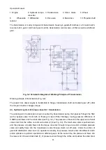
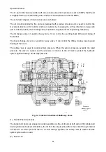
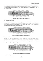
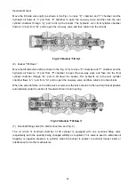
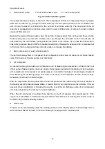
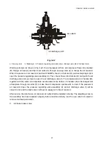
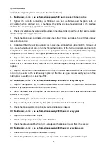
Fig.3-17 Interior Structure of Overload Filling Valve
8.
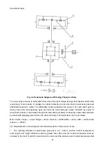
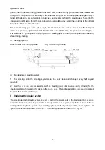
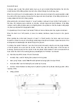
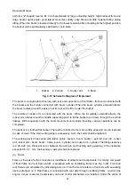
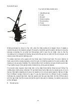
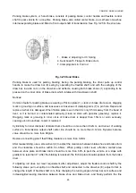
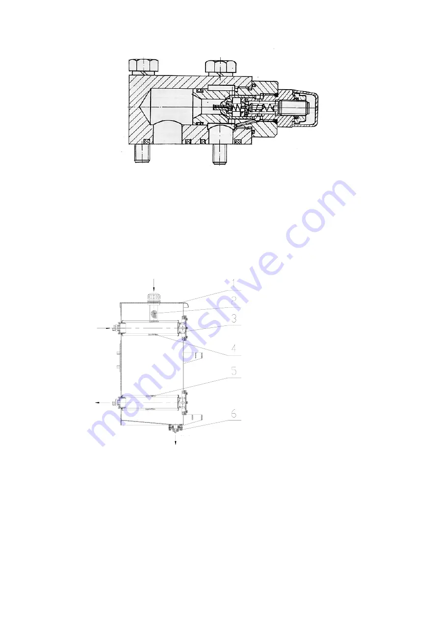
The oil tank (see Fig. 3-18), with a capacity of 80L, is shared between the working device and
steering system. Air filter used to refuel is on the top, two joints used to fit hydraulic system inlet/return
pipe are located in the left, and two oil filters are fitted to the inside to remove impurities in the oil. To
clean oil filters periodically, it only needs to remove 6 bolts on right flange cover to remove the cover
and to pull out oil filter. Drain plug on the bottom of oil tank is used for periodic oil-replacing and
cleaning.Replace oilonce per year (2400h) at least
Fig. 3-18 Hydraulic Oil Tank
1.
Hydraulic oil tank body
2. Air filter
3. Flange cover
4. Oil return filter
5.
Oil suction filter
6. Plug
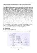
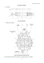
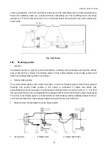
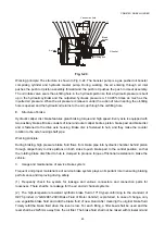
VII. Implement&frame
(i) Implement
The working device for the loader is mainly composed of bucket, pull rod, boom and rocker arm. See
Fig. 3-19. The tilt mechanism for the loader is provided with a single rocker arm and single pull rod and
Fill oil
Oil return
Oil outlet
Drain oil


