
CDM816D WHEEL LOADER
59
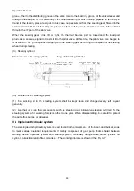
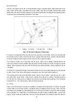
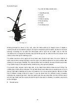
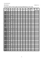
steering mechanism, front and rear frames rotate around the articulating axis to realize steering. Rear
frame and oscillating frame are connected through articulating pin. The oscillating frame can swing
up/down by 10° around the pin center so as to make the loader remain stable even when traveling on
rough roads.
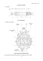
Fig. 3-20 Frame
VIII.
Braking system
i.
General
The braking system is used for vehicle deceleration or braking during traveling and long-time vehicle
stop on flat ground or slopes. The braking system of this loader includes service brake system (foot
brake) and parking brake system (hand brake).
ii
Service brake system
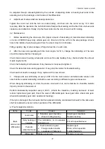
The service brake system, also called foot brake, is used for frequent speed control during general
traveling. The service brake system of this loader is composed of caliper disc brake, gas
pushedoilbooster pump and pedal. Front/rear wheel braking torque conversion ratio is 1:1. The front
and rear wheel brakes are exchangeable and equipped with front and rear booster pumps respectively.
The whole service brake system is characterized by stable braking, safety, reliability, simple structure,
convenient maintenance, easy sewage disposal and good recovery performance.
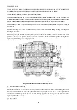
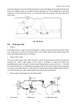
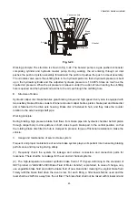
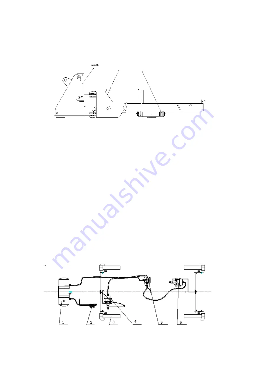
1.
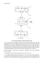
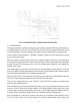
Main structure and principle of service brake system:
1.
Air reservoir
2. Relief valve
3. Caliper disc brake
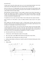
Rear frame
Front frame
Sub-frame


