background image

WSDA

®

-Base-104

®

USB Base Station

User Manual

System Operational Overview

25

3.8.1

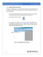
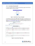
Connecting to SensorCloud™

To connect to SensorCloud go to the SensorCloud website log-in page, and enter the log-in

credentials. Register as a new user if needed.

http://sensorcloud.com/log-in/

Figure 15 - SensorCloud™ Log-in or Register

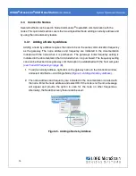
The SensorCloud interface has

six main views

. When logging in as a registered user, the

Device view is the default. Navigate to other views by clicking the view name at the top of the

page (

Figure 16 - SensorCloud™ Menu Views

). The Data and Settings views are only

available once a device is selected from the device list.

Figure 16 - SensorCloud™ Menu Views

Summary of Contents for WSDA-Base-104

Page 1: ...LORD USER MANUAL WSDA Base 104 Wireless USB Base Station ...

Page 2: ...4 45 3DM GX4 3DM RQ1 3DM GQ4 AIFP Ask Us How Bolt Link DEMOD DC DVRT DVRT Link DEMOD DVRT EH Link EmbedSense ENV Link FAS A G Link G Link2 HS Link IEPE Link Inertia Link Little Sensors Big Ideas Live Connect LXRS MathEngine MicroStrain MVEH MXRS Node Commander PVEH RHT Link RTD Link SensorCloud SG Link Shock Link Strain Wizard TC Link Torque Link V Link Watt Link Wireless Simplicity Hardwired Reli...

Page 3: ...munication 13 3 4 Connect to Nodes 14 3 4 1 Adding a Node by Address 14 3 4 2 Using Node Discovery 15 3 5 Channel Configuration 16 3 6 Sampling Settings 18 3 7 Data Acquisition 19 3 8 Data Handling 24 3 8 1 Connecting to SensorCloud 25 3 8 2 Sensor Data Files 28 4 Gateway Communication and Settings 29 4 1 Verify Gateway Communication 30 4 2 Gateway Communication Timeout 30 4 3 Removing a Gateway 3...

Page 4: ...5 1 Installation Recommendations 38 5 2 Optimizing the Radio Link 39 5 2 1 Range Test 40 6 Troubleshooting 41 6 1 Troubleshooting Guide 41 6 2 Communications Ports in Windows 46 6 3 Technical Support 48 7 Maintenance 49 8 Parts and Configurations 50 8 1 Standard Models 50 8 2 Gateway Accessories 50 8 3 Wireless System Equipment 51 8 4 Product Ordering 52 9 Specifications 53 9 1 Physical Specificat...

Page 5: ...WSDA Base 104 USB Base Station User Manual 10 1 ESD Sensitivity 56 10 2 Disposal and Recycling 56 11 References 57 11 1 Reference Information 57 11 2 Glossary 58 ...

Page 6: ...terface with many types of sensors including accelerometers strain gauges pressure transducers load cells torque and vibration sensors magnetometers 4 to 20mA sensors thermocouples RTD sensors soil moisture and humidity sensors inclinometers and orientation and displacement sensors Some nodes come with integrated sensing devices such as accelerometers System sampling capabilities are IEEE 802 15 4...

Page 7: ...rts all data acquisition sessions between wireless nodes and host computers including continuous sampling burst sampling and datalogging The gateway also facilitates precision sampling synchronization between sensor nodes by transmitting a continuous system wide timing reference known as the beacon The WSDA Base 104 utilizes a USB interface to transfer data from the wireless nodes to a host comput...

Page 8: ...ging sensor nodes and a USB cable for interfacing with the host computer or network For a complete list of available configurations accessories additional system products and ordering information see Parts and Configurations on page 50 Item Description Quantity A WSDA Base 104 USB Base Station 1 B Standard whip antenna FCC compliant 1 C USB cable 1 D Node power supply and plug adapter kit 1 Node C...

Page 9: ...on the front of the WSDA Base 104 The following table describes indicator behavior Figure 2 Ports and Indicators Indicator Behavior Node Status Device Status Indicator OFF Gateway is off ON green Gateway is powered idle Flashing blue Sync sampling beacon enabled or incoming data from other sampling modes Flashing red WARNING another gateway beacon is detected on the same frequency Table 2 Basic In...

Page 10: ... available for data acquisition from the wireless sensor network SensorCloud and Node Commander SensorCloud is an optional web based data collection visualization analysis and remote management platform based on cloud computing technology Node Commander is used for configuring gateways and nodes selecting sampling modes and parameters initializing data acquisition and viewing and saving data The o...

Page 11: ...nnect is a TCP IP to serial conversion tool that translates the communications between Node Commander and an Ethernet gateway This program is only used with the WSDA 1500 LXRS or other Ethernet gateways l WSDA Data Downloader is used to download acquired data from the flash memory card embedded in an applicable gateway to a host computer This program is only used with the WSDA 1500 LXRS or other E...

Page 12: ...computer with access to the data acquisition software such as Node Commander and SensorCloud For a connections overview refer to Figure 3 System Connections The sensor node gateway and software selection are application dependent but the basic interfaces are the same For a connections overview using the WSDA Base 104 refer to Figure 3 System Connections Users can also write custom programs by util...

Page 13: ... in 1 Power is applied to the gateway through the USB connection Verify the gateway status indicator is illuminated showing the gateway is connected and on 2 Open the Node Commander software 3 The gateway should appear in the Controller window automatically with a communication port assignment Figure 4 USB Gateway Communication If it is not automatically discovered verify the port is active on the...

Page 14: ...rchased The gateway s initial frequency setting is indicated in the documentation that is included when it is purchased The frequency setting can also be checked once gateway communication is established with the host computer see Transmit Frequency on page 33 1 To add a node by address right click on the gateway name in the Controller window and select Add Node Add Single Node Figure 5 Adding a N...

Page 15: ...le node discovery For more information see Troubleshooting Guide on page 41 1 Right click on the gateway name and select Add Node Node Discovery Figure 6 Using Node Discovery 2 Using the power switch turn on the node Within a few seconds the node will transmit a message with its operating frequency 3 When the device status indicator on the node ends the rapid flash sequence and begins pulsing at o...

Page 16: ...indicates the sensor channel number The check box is used to enable the channel and select it for sampling The icon next to the check box describes the channel type inherent to the node being used In the following example Figure 7 Node Channels Menu a1 analog differential channel icon a2 analog single ended channel icon and a3 temperature channel icon b Current channel configuration The Data Outpu...

Page 17: ...ctronics and data flow c Conversion Coefficients defines the type and units of the measurement being made d PGA Settings These settings determine what gain is applied to the sensor measurement and set the position of the no load baseline measurement for the sensor signal It is only available for differential input channels with gain amplifiers e Calibration values includes the slope offset scale a...

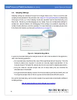
Page 18: ...ge 57 Figure 9 Sample Settings Menu In general when determining what sample mode and rate is most suitable for the application refer to the following guidelines l Use a sample rate at least twice the value of the target measurement frequency This is the minimum sample rate required to produce an accurate digital representation of the measured signal The higher the sample rate the more accurate the...

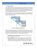
Page 19: ... Right click on the nodes and select Sample Synchronized Sampling Figure 10 Starting a Sampling Session When a synchronized sampling session is started the sampling menu appears and includes settings to enable optional sampling features configure nodes and to specify where the data will be saved The built in bandwidth calculator displays the total bandwidth used by the nodes selected for synchroni...

Page 20: ...ted bandwidth used by all the nodes The bandwidth changes as nodes are added removed and settings changed f Enable Beacon on Start When synchronized sampling is started the nodes wait for the first beacon transmission to initiate sampling When this option is selected default the gateway beacon is enabled and will begin transmitting at a fixed interval when sampling is started Disabling the beacon ...

Page 21: ...ing Data View Figure 12 Synchronized Sampling Data View a Device status Node sampling mode and gateway status are displayed in parentheses next to the device name b Node information includes node serial number and sampling statistics Right click on the node name for more menu options such as Stop Nodes c Data is a display of the sampled data with each channel in its own column d Radio strength ind...

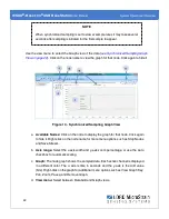
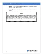
Page 22: ...ing Graph View a Available Nodes Click on the node to display the graph for that node Click again to hide it Right click on the node name for more menu options such as Stop Nodes and Save Stream b Axis range Select the x axis width and y axis zoom percentage or use the Auto check box for automatic scaling c Graph The node graph shows the sampled data Each active channel is displayed in a different...

Page 23: ...d X is used to exit the sampling window and or end sampling NOTE Once sampling has started it will continue as configured without the need to leave Node Commander open However if the node is powered off and is not configured to sample on boot up data acquisition will end and must be restarted in Node Commander To resume viewing data after the sampling window has been closed use Monitor Mode found ...

Page 24: ...reservation of data Features include time series and visualization graphing automated alerts and data interpretation tools such as data filtering statistical analysis and advanced algorithm development with the integrated MathEngine interface Leveraging the open source API SensorCloud can also be used to collect data from other LORD MicroStrain sensor products or third party systems Basic SensorCl...

Page 25: ...ser if needed http sensorcloud com log in Figure 15 SensorCloud Log in or Register The SensorCloud interface has six main views When logging in as a registered user the Device view is the default Navigate to other views by clicking the view name at the top of the page Figure 16 SensorCloud Menu Views The Data and Settings views are only available once a device is selected from the device list Figu...

Page 26: ...he LORD MicroStrain CSV format Data This view is only available after a device is selected It displays data that is collected from sensor nodes or uploaded from files Data selections are listed by node channel or a user defined label and can be enabled for display in the graph window The interactive graph has navigational features such as panning zooming and an overview graph for single click acce...

Page 27: ...r processing Users can write their own algorithms for custom applications Refer to the MathEngine website for more information http sensorcloud com mathengine Figure 18 MathEngine View Figure 19 FFT Graph in SensorCloud For more information about SensorCloud features and navigation refer to the SensorCloud website or contact LORD MicroStrain Technical Support http sensorcloud com ...

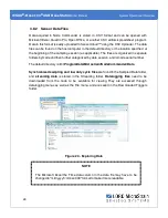
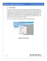
Page 28: ...he files are organized in separate folders by mode and then further categorized by date session and or node serial number The default directory is C ProgramData Microstrain NodeCommander Data Synchronized sampling and low duty cycle files are found in the Sampled Data folder and streaming data is stored in the Streaming folder Datalogging files need to be downloaded from the node to be available f...

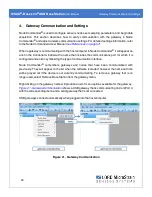
Page 29: ... the communications port for which it is configured and an icon symbolizing the type of communication interface Node Commander remembers gateways and nodes that have been communicated with previously They will appear on the list when the software is started however the name and icon will be grayed out if the device is not currently communicating To remove a gateway that is no longer used select Re...

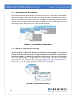
Page 30: ...ht click on the gateway name and select the command Figure 22 Verify Gateway Communication 4 2 Gateway Communication Timeout Node Commander will attempt to establish communication with the gateway for the amount of time set as the communication timeout the default setting is 20 milliseconds If communication cannot be established try adjusting this value for a longer timeout Right click on the gate...

Page 31: ...mation such as the model type serial number radio type operating frequency current communications port and firmware revision is found in the gateway Information window Right click on the gateway name and select Configure Configure Base Station There is also a Label field to give the gateway a unique name which is useful when there are multiple gateways in the system Gateway transmit power can also...

Page 32: ... also reduces the wireless communication range between the gateways and nodes NOTE Actual range is highly dependent of how the nodes and gateways are installed and the conditions in the surrounding environment see Range Test on page 40 Setting Power Output Maximum Range Extended 16 dBm 39mW 2 km Standard 10dBm 10mW 1 km Low 0dBm 1mW 70 m Table 3 Transmit Power Settings The transmit power setting f...

Page 33: ...tially powered on and it will broadcast on all channels As long as the node is powered on after activating the Node Discovery feature the gateway will link to it and remember the channel setting for future node queries l Manually matching the node and gateway frequency channels is required in some applications For example when sending broadcast messages from the gateway to multiple nodes including...

Page 34: ...and displays the data This is useful if the node was configured to start sampling on boot up or if the data acquisition screen was closed without stopping the node It is a way to enter the data and graph view windows after data acquisition has already begun The gateway will only monitor nodes that are on the same frequency channel that it is on All nodes on that frequency will automatically be dis...

Page 35: ...roadcast commands Network broadcast functions include communications sampling and configuration commands Network broadcast commands are found in the gateway menu Right click on the gateway name and select Network Broadcast Then select the desired category and command Sample l Synchronized Sampling Start l Low Duty Cycle Start l Armed Datalogging l Trigger Datalogging Session l Erase Communicate l ...

Page 36: ...ion times between the gateway and nodes will be consistent because of the accuracy of the embedded RTC clocks Nodes must be on the same transmission frequency channel as the gateway to receive the beacon broadcast command When the beacon is active the gateway device status indicator will pulse blue once per second When the nodes connected to the gateway are in synchronized sampling mode the networ...

Page 37: ...the online network bandwidth calculator to determine the bandwidth capacity for a particular system configuration http www microstrain com configure your system 4 9 2 Synchronized Sampling with Multiple Gateways If synchronization is desired between gateways it is recommended that a WSDA 1500 LXRS gateway be used because they can be configured to reference external time sources and therefore get p...

Page 38: ...n a ruggedized outdoor enclosure purchased separately It is designed for desktop use although it can be mounted in any orientation as required by the application It is recommended that it is mounted in a way that optimizes the wireless communications typically with the antenna pointing upward For more information see Optimizing the Radio Link on page 39 Figure 31 Gateway Installation ...

Page 39: ...n the node and gateway antennas as best as possible Try to avoid obstructions between the antennas such as buildings terrain vegetation or other physical barriers Increase the mounting height of the node or antenna to allow a clearer LOS path to the gateway Height above the ground is also important because reflections off of the ground can interfere at the receiver Generally the higher above the g...

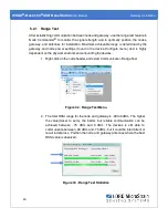
Page 40: ...e Configure menu and is highly dependent on the physical environment surrounding the devices 1 Right click on the node header and select Communicate Range Test Figure 32 Range Test Menu 2 The total RSSI range for the node and gateway is 90 to 0dBm The higher the value closer to zero the better but reliable communication can be achieved between 75 dBm and 0 dBm The devices is still able to communic...

Page 41: ...WSDA Base 104 USB Base Station User Manual Troubleshooting 41 6 Troubleshooting 6 1 Troubleshooting Guide ...

Page 42: ... need to be replaced Contact LORD MicroStrain Technical Support See Technical Support on page 48 1 5 node or gateway is damaged If all power settings and connections have been verified and the node is still unresponsive contact LORD MicroStrain Technical Support See Technical Support on page 48 2 COMMUNICATION no communication to the gateway or node 2 1 node or gateway has no power Verify the node...

Page 43: ...tting the node back in a sample or sleep state 2 4 node is out of range Perform a bench test with the node in close proximity to the gateway to verify they are operational For range test and installation recommendations see Range Test on page 40 The system has been tested to operate with the node and gateway up to 2 km apart with clear line of sight 2 5 node is not in normal boot mode If the node ...

Page 44: ...ain Technical Support See Technical Support on page 48 3 DATA ACQUISITION sensor data is missing or incorrect 3 1 no communication to node or gateway Verify connections and power to the node and gateway Verify they are powered on and communicating with the software Enter a configuration menu to verify that the node can be accessed 3 2 sampling settings are incorrect If the sampling mode rate or du...

Page 45: ...ensor when purchased If possible perform a field verification of the sensors by applying known loads and comparing the measured values In the channel configuration settings verify that the calibration calculations are correct Verify that the gain and offset range are correct and that the baseline offset is set with Auto Balance as applicable Verify that the calibration values slope and offset are ...

Page 46: ... virtual communications port in Windows Windows Device Manage can be used to determine what communication port the gateway is connected to 1 Click on the Windows Start icon and select Control Panel 2 Navigate to the System menu and select Device Manger The menus may appear different depending on the version of Windows and the View settings Figure 34 Windows System Menu ...

Page 47: ...th the COM port number A USB gateway will be displayed as USB to UART Bridge COM X A serial gateway will be attached to the Communications Port COMX An Ethernet gateway will be connected to a Virtual Serial port COMX If no port is listed the port is not recognized by the computer and no gateway communication can be established Figure 35 Windows Device Manger Menu ...

Page 48: ...d product manuals http www microstrain com support_overview aspx For further assistance our technical support engineers are available to help with technical and applications questions Technical Support sensing_support LORD com Phone 802 862 6629 Fax 802 863 4093 SKYPE microstrain wireless support Live Chat is available from the website during business hours 9 00 AM to 5 00 PM Eastern Time US Canad...

Page 49: ...l Maintenance 49 7 Maintenance There are no user serviceable parts on the WSDA Base 104 For device service and repair contact LORD MicroStrain Technical Support see Technical Support on page 48 Opening the device will void the product warranty ...

Page 50: ...rain Part Number WSDA Base 104 LXRS Wireless USB Base Station 6307 1040 WSDA Base 102 LXRS Wireless RS232 Base Station 6307 1020 WSDA Base 101 LXRS Wireless Analog Base Station 6307 1010 8 2 Gateway Accessories Description LORD MicroStrain Part Number Standard whip antenna FCC compliant 9010 0049 USB cable Micro B 1 meter long 9022 0029 Node charging power supply 9011 0024 Node power supply intern...

Page 51: ...ut Gateway 6307 1010 G Link LXRS Wireless Accelerometer Node various models G Link2 LXRS Wireless Accelerometer Node various models SG Link LXRS Wireless 2 Channel Analog Input Sensor Node various models SG Link OEM Wireless 2 Channel Analog Input Sensor Node various models SG Link RGD Ruggedized Wireless Analog Sensor Input Node various models V Link LXRS Wireless 7 Channel Analog Input Sensor No...

Page 52: ...MicroStrain website by navigating to the product page and using the Buy feature http www microstrain com wireless For further assistance our sales team is available to help with product selection ordering options and questions Sales Support sensing_sales LORD com Phone 802 862 6629 Fax 802 863 4093 9 00 AM to 5 00 PM Eastern Time US Canada ...

Page 53: ...se 104 USB Base Station User Manual Specifications 53 9 Specifications 9 1 Physical Specification Dimensions 120 3 mm x 70 4 mm x 87 9 mm Weight 123 grams Enclosure Environmental Rating General purpose indoor ...

Page 54: ...ption available for use outside the U S A limited to 10 dBm 10 mW RF communication protocol IEEE 802 15 4 Power consumption Idle 45 7 mA Eight active node channels operating at 256 Hz low duty cycle 65 6 mA Operating temperature 40 C to 85 C electronics 30 C to 70 C enclosure antenna Physical Specifications Dimensions 88 mm x 70 mm x 20 mm without antenna Weight 123 grams Enclosure material Black ...

Page 55: ... Following the 802 15 4 standard these frequencies are aliased as channels 11 through 24 For all newly manufactured nodes the default setting is 2 425 GHz channel 15 For standard models radiated transmit power is programmable from 0 dBm 1 mW to 16 dBm 39 mW A low transmit power option is available for use in Europe and elsewhere and is limited to 10 dBm 10 mW The radio complies with FCC Part 15 US...

Page 56: ...antenna and connectors Use proper grounding techniques when handling If an ESD event occurs and operation has been interrupted reset the device by cycling power to it and or restarting the operational mode in the system software 10 2 Disposal and Recycling The WSDA Base 104 contains internal batteries printed circuit boards and electronic components These items are known to contain toxic chemicals...

Page 57: ...http www microstrain com configure your system SensorCloud Overview http www sensorcloud com system overview MathEngine Overview http www sensorcloud com mathengine LORD MicroStrain Wireless Sensors Network Software Development Kit http www microstrain com wireless sdk Product Datasheets http www microstrain com wireless sensors Product Manuals and Technical Notes http www microstrain com support ...

Page 58: ... correction or calibration factor Configuration a general term applied to the node indicating how it is set up for data acquisition It includes settings such as sampling mode and rate number of active channels channel measurement settings offsets hardware gain and calibration values Continuous Sampling a mode of operation in which the node is sampled continuously until stopped or continuously for ...

Page 59: ...that orchestrates command and control of the attached devices or networks LED Light Emitting Diode is an indicator light that is used in electronic equipment LOS Line of Sight is used in radio communications to describe the ideal condition between transmitting and receiving antennas in a radio network As stated it means the antennas are in view of each other with no obstructions LXRS Lossless Exte...

Page 60: ...nuous string of pings used to validate communication between the gateway and the node over distance and obstruction Real Time Clock RTC a computer clock that keeps track of the current time RFI Radio Frequency Interference is a disturbance in an electrical circuit due to electromagnetic induction or radiation RSSI Received Signal Strength Indication is a measurement of the transmission power in a ...

Page 61: ...e a user defined start and end time or continuous continued until the power is cycled on the node Synchronized Sampling a sampling mode that automatically coordinates all incoming node data to a particular gateway This mode is designed to ensure data arrival and sequence Transmission rate the number of data packets per transmission window measured in seconds Depending on the sampling mode and sett...

Reviews: