8 Installation
Installation 9
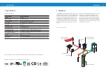
Configure the PS2 controller with PumpScanner as
instructed in the PS2 and PumpScanner manuals. To
configure automatic switching of the power supply
between solar and grid power navigate to “Feature
Settings” in PumpScanner and expand the “Switch
output”.
Under the tab “Sun Sensor is triggered”, select “24/7
operation with PowerPack”. Define the irradiation
threshold for which the PowerPack should be
activated. See figure 4 for examples.
The wires for connecting the switch output of the
PS2 controller with the remote on/off terminals of
the PP2000S must be 1 mm² (AWG18) or larger.
5 Installation
5.1 Mounting
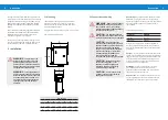
The PowerPack should be mounted on a wall or
panel close to the pump controller in a vertical
position. The unit must be protected from direct
rainfall and direct sunlight.
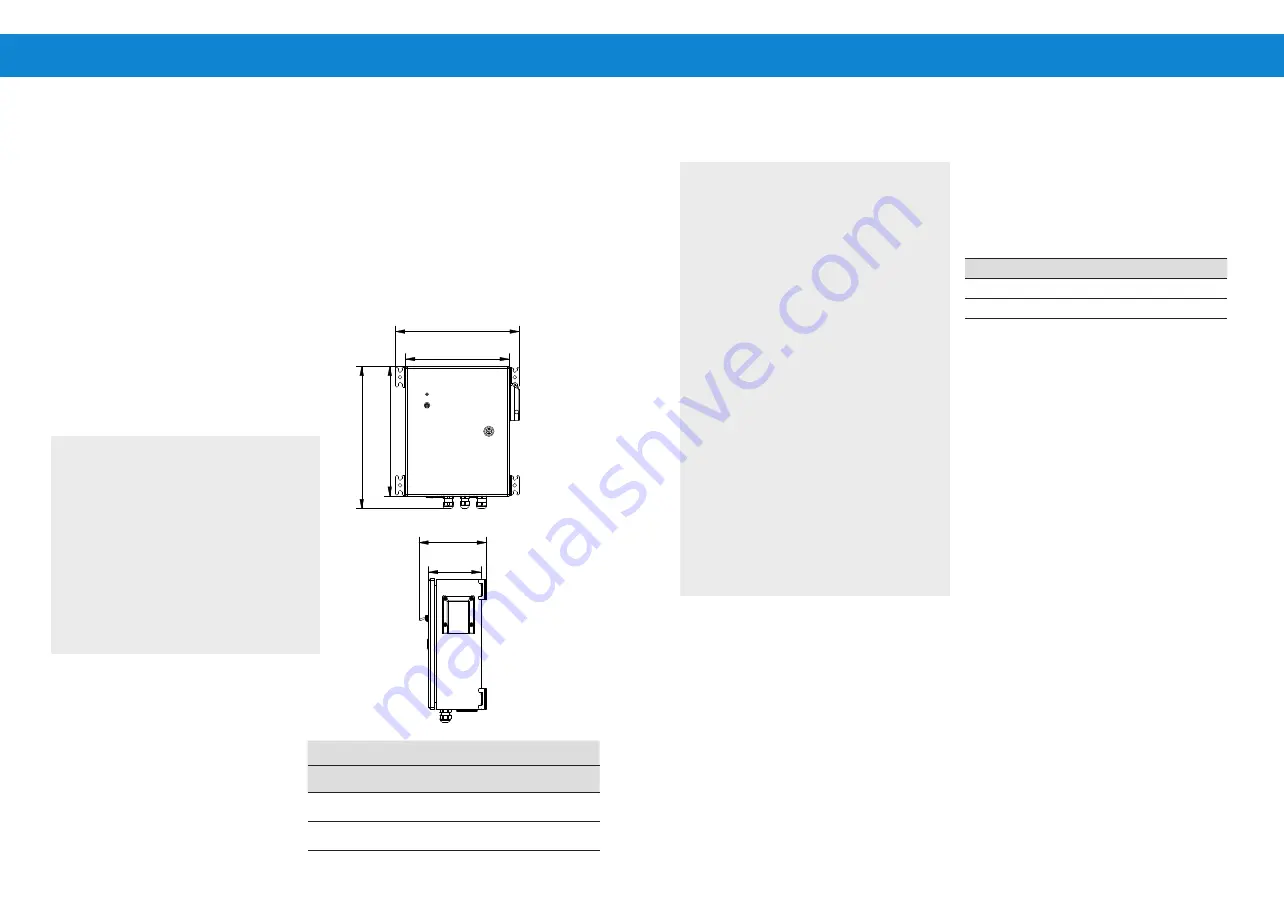
Fixing pattern for holes: 310 x 292 mm / 12.2 x 11.5 in
Figure 5: Product dimensions
l
WARNING
– Beware of high voltage!
Hazardous electricity may be present
and can shock, burn or cause death!
Only authorized and qualified personnel
should operate the system.
a
CAUTION
– The PowerPack should
only be connected to power after correct
wiring or the controller may be damaged.
CAUTION
– Do not connect any
electrical load to the PV generator other
than the LORENTZ pump controller and
PowerPack. Connecting the battery
charger, active solar tracker controller,
electric fence charger or other loads
simultaneously with LORENTZ PS2
systems may interfere with the
controller and prevent proper operation.
CAUTION
- Measure the voltage
before connecting power to the
PowerPack. Follow the guidelines
included in this manual regarding
maximum PV input voltages.
CAUTION
- Do not connect the PV
modules to the DC output as it may
damage the PV modules.
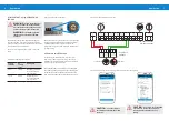
5.2 Connections and wiring
DC Solar Input
- Connect the PV modules to “SOLAR
POWER IN”, paying close attention to the polarity.
Check the voltage from the PV generator. The voltage
must not exceed the open circuit values listed in
table 3 below.
Table 3: Maximum PV input
Controller
PP2000S
PS2-600
150 V DC
PS2-1800
200 V DC
Every solar pump system must be equipped with
a properly sized DC disconnect switch. The switch
must be installed between the PV generator and the
PowerPack.
AC Input
- Connect AC power to the terminals (L) line
and (N) neutral. Before connecting to grid, check that
the grid connection is properly protected with a fuse
and if required with an ELCB (Earth leakage circuit
breaker). All electrical connections must meet local
and national electrical standards.
Grounding
– Ensure the PowerPack is correctly
grounded to meet local and national ectrical
guidelines. The dedicated GND terminal on the AC
input is the grounding connection.
DC power out
- Connect the Powerpack DC OUT via
an appropriate DC disconnect (or PV disconnect) to
the POWER IN + - terminals of the PS2 controller.
A
D
B
E
C
F
A= 280mm
B= 350mm
C= 140mm
D= 334mm
E= 384mm
F= 180mm
Product Dimensions for Installation Manual
A
D
B
E
C
F
A= 280mm
B= 350mm
C= 140mm
D= 334mm
E= 384mm
F= 180mm
Product Dimensions for Installation Manual
l
WARNING
– This device must be
installed, connected and serviced by
qualified personnel only. Ensure all
power sources are disconnected when
making connections to this unit. Follow
all appropriate electrical codes.
WARNING
– For best performance
and to avoid over temperature shut off,
install the PowerPack in a location that
is shaded from direct sun. Allow free
air circulation around the ventilation
openings on the side and bottom of
enclosure.
Dimensions
A
B
C
D
E
F
mm
280
350
140
334
384
180
in
11
13.8
5.5
13.1
15.1
7.1


