background image

25

User Manual

3

For the New User

In order to get started using your chart plotter, you must do the following

things:

1) Your chart plotter must have been installed properly according to the

installation  instruction on Par. 6.2.

2) You must have performed the proper settings for use with your position-

ing instrument (see Par. 2.5) and inserting the C-CARD for navigating in area you

wish (see Par. 2.6).

3) You must have Power On to the chart plotter and adjust the brightness

and contrast of the display (see Par. 2.2 and 2.3).

Once this is done, you can use your chart plotter for navigation.

3.1 SCREEN DISPLAY CONFIGURATION

Use '<PAGE>' to select the desired page, in two different ways:

1) by showing the next or the previous page as the relative key is pressed

2) by selecting the page from the Page Selection menu

The desired way to select the page is set by changing "Page Preview" follow-

ing the procedure:

'MENU' + "BASIC SETTINGS" + 'ENTER' + "PAGE PREVIEW" + 'ENTER'

When "Page Preview" is "Off", '<PAGE'/'PAGE>' allows setting the pre-

vious/next page (1). When "Page Preview" is "On", '<PAGE>' opens the Page

Selection menu (2), on which the icons representing the pages are shown: the icon of

the currently selected page is identified by a bold frame; move the selection with the

Cursor keys or '<PAGE>', the name of the currently selected page icon is shown

in the lower side of the Page Selection menu. Pressing 'ENTER' the Page Selection

menu is closed and the currently selected page is activated.

Summary of Contents for MAGNUM PLUS

Page 1: ... CODE S3egLZctcms_0ww 1128d970 A01 160407 USER MANUAL Copyright 2007 LORENZ ELECTRONICS Italia All rights reserved Printed in Italy No part of this publication may be reproduced or distributed in any form or by any means or stored in a database or retrieval system without prior written permission of the publisher ...

Page 2: ...lease contact the Company s customer service or your local dealer The chart plotter is not built water proof Please give attention to avoid water intrusion into the chartplotter Waterdamageisnotcoveredbythewarranty Extensiveexposuretoheatmayresultin damage to the chartplotter Connection to the power source with reversed polarity will damage the chart plotter severely This damage is not covered by ...

Page 3: ...tion 21 2 5 ADDITIONAL C CARDS 22 2 5 1 Inserting C CARD 22 2 5 2 Removing C CARD 23 3 For the New User 25 3 1 SCREEN DISPLAY CONFIGURATION 25 3 1 1 Charts and Text Area 26 3 1 2 Depth Graph 27 3 1 3 GPS Data Page 28 3 1 4 Navigation Data Page 28 3 1 5 Graphic Data Rolling Road Page 29 3 1 6 The Wind Data Page 29 3 2 A B C D FUNCTION 29 3 2 1 Inserting the A B C D points 30 3 2 2 Deleting the A B ...

Page 4: ...s 46 3 4 7 7 Finding POIs 46 3 4 7 8 Finding Lakes By Names 46 3 4 7 9 Finding Lakes Information 46 4 For the Experienced User 49 4 1 MORE ABOUT CREATING AND USING ROUTES 49 4 1 1 Waypoints 49 4 1 1 1 Adding Waypoint 49 4 1 1 2 Creating a route 50 4 1 1 3 Deleting Waypoint 50 4 1 1 4 Deleting route 51 4 1 1 5 Distance and Bearing to Target 51 Time To Go 52 Deleting Target 52 4 1 1 6 Moving Waypoin...

Page 5: ...4 4 3 3 Editing EBL VRM 64 4 4 MORE ABOUT A B C D FUNCTION 64 4 4 1 Inserting the A B C D points 64 4 4 2 Deleting the A B C D Points 64 4 4 3 Deleting the A B C D Segment 65 4 4 4 Moving the A B C D points 65 4 4 5 Inserting the A B C D points 65 4 4 6 Navigating on the A B C D points 65 4 5 USING THE TRACK FUNCTIONS 65 4 5 1 Selecting active Track 65 4 5 2 Enabling Track storing 66 4 5 3 Display...

Page 6: ...S SYSTEM DEFINITIONS 76 4 9 2 AIS MENU 77 4 9 2 1 Display 77 4 9 2 2 Activation range 77 4 9 2 3 CPA Alarm 78 4 9 2 4 CPA Limit 78 4 9 2 5 TCPA Alarm 78 4 9 2 6 TCPA Limit 78 4 9 3 TO SET THE CHART PLOTTER FOR RECEIVING AIS 78 4 9 4 QUICK INFO ON AIS TARGET 78 4 10 C STAFF 79 4 11 C WEATHER SERVICE 79 4 11 1C WEATHER SERVICE MENU 80 4 11 1 1 Download 80 Select Country to Call 80 SIM PIN 80 Downloa...

Page 7: ...IRING 114 6 4 TYPICAL CONNECTIONS POWER I O Connector 115 6 4 1 GPS Connections 115 6 4 2 Autopilot Connections 115 6 4 3 External NMEA Connections 116 6 4 4 C COM Connection 116 6 4 5 External Alarm Connection 117 6 5 SYSTEM TEST 117 6 5 1 RAM Menu 117 6 5 2 DIM Menu 118 6 5 3 CARTRIDGES 118 6 5 4 SERIAL PORTS 119 6 5 5 External Alarm 119 6 5 6 Display Settings 119 A Trouble shooting 121 Analytic...

Page 8: ...10 User Manual ...

Page 9: ...s listed by keys sequence with the menu names enclosed between inverted commas for example MENU BASIC SETTINGS ENTER INPUT OUTPUT ENTER means press the MENU key using the cursor key to select the Basic Settings menu press the ENTER key using the cursor key to select the Input Output menu and then press the ENTER key Terms and functions underlined for example Target are explained in the Chapter 5 1...

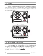
Page 10: ... not valid three rapid beeps sound indicates that no response is available Fig 1 2 MAGNUM Pro Fig 1 2a MAGNUM Plus 1 3 IF YOU NEED ASSISTANCE If your chart plotter does not operate properly go to the System Test on Par 6 5 Most common operating difficulties can be diagnosed using these tests If you still need assistance call your local dealer reporting the Software Release and Cartography informat...

Page 11: ...ts highways railways etc Nav Aids depth areas territorial water areas etc by reading them from a special data C CARDs contact your local dealer All units must have the WorldWide Background upload function that is activated from the system Worldwide Background Update The System Update menu is entered from the About page To select this menu fol low the procedure Plug the special data C CARD MENU Abo...

Page 12: ...14 User Manual ...

Page 13: ...uations returns to the previous menu or leaves a menu without making changes If you are not into a menu if the GPS computing a valid fix position and the chart plotter is not in Home mode pressing CLEAR sets Home mode When Home called also Navigate mode is set the cursor is not shown any more and all cartographic functions zoom scroll etc are leaded by the fix position The fix is centered in the m...

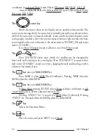
Page 14: ...CLEAR If in Home Navigate mode it allows to exit from Home mode The and keys Press ZOOM IN shows more details of a smaller area by changing the chart scale and zooming in on your display Press ZOOM OUT to operate simi larly to the ZOOM IN except in reverse changing the scale and showing a wider otherwise less detailed view The key ONLY ON MAGNUM PLUS Press MOB to place MOB Man OverBoard Pressing M...

Page 15: ...AYPOINT place Waypoint EBL VRM place EBL and VRM C WEATHER shows C Weather Forecast mode Press and release FUNCTION executes the function that was assigned Note The selections Mark Event Waypoint and EBL VRM are available even if Advanced Functions is Off The key ONLY ON MAGNUM PRO Pressing TRACK enables or disables the track storing The key If Radar is connected pressing RADAR selects the Radar p...

Page 16: ...ice pages is displayed reminding you that the chart plotter is only an aid to navigation and should be used with appropriate prudence The electronic charts are not intended to substitute for the official charts Then the cartographic screen is displayed 2 2 2 TURNING OFF Press the right side of POWER and hold for 3 seconds a countdown timer appears on the screen if you release the key before the co...

Page 17: ...N the default setting is 4800 N81 N and press ENTER to confirm If you are connecting the model Smart DGPS WAAS Receiver GPH00 select MENU BASIC SETTINGS ENTER INPUT OUTPUT ENTER PORT 3 INPUT ENTER NMEA 4800 N81 N ENTER 2 4 2 AUTOPILOT CONNECTIONS To connect the Autopilot to the serial Port 1 see the following picture Fig 2 4 2 Autopilot Connections on Port 1 To choose your preferred setting follow...

Page 18: ...83 4800 N81 N and press ENTER to confirm 2 4 3 EXTERNAL NMEA CONNECTIONS To connect the External NMEA to the serial Port 1 see the following picture Fig 2 4 3 External NMEA Connections on Port 1 To choose your preferred setting follow the procedure MENU BASIC SETTINGS ENTER INPUT OUTPUT ENTER PORT 1 INPUT ENTER Then choose your preferred setting among the NMEA available settings NMEA1200 N81 N NME...

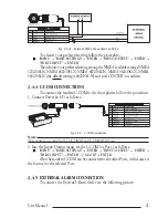
Page 19: ...to confirm 2 4 4 C COM CONNECTIONS To connect the modem C COM to the chart plotter follow the procedure 1 Connect Power I O as follows Fig 2 4 4 C COM Connection Note The connection is valid for the C COM IR and C COM RS232 too 2 Into the Input Output menu set the C COM for Port 1 as follows MENU BASIC SETTINGS ENTER INPUT OUTPUT ENTER PORT 1 INPUT ENTER C COM ENTER Also the modem C COM can be con...

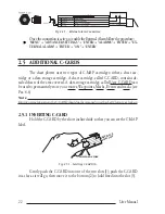
Page 20: ...ed A data storage cartridge called User C CARD can be used to permanently store your routes Waypoints Marks Events and tracks see Par 4 6 Note During normal operations the C CARD should not be removed since the chart plotter may lock up 2 5 1 INSERTING C CARD Hold the C CARD by the short inclined side so that you can see the C MAP label INSERTION DIRECTION INCLINED SIDES cl as s da te co de se r n...

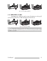
Page 21: ... move it to the top 2 until you hear a click the C CARD will ejected out of the slot 3 1 2 4 date code ser n N T date code ser n clas s 5 3 Fig 2 5 2 Removing C CARD Note C MAP is continuously creating new charts and revising old ones If you wish to receive information on the newest available charts you can write for the catalog of available C MAP C CARD at your dealer ...

Page 22: ...24 User Manual ...

Page 23: ...AGE to select the desired page in two different ways 1 by showing the next or the previous page as the relative key is pressed 2 by selecting the page from the Page Selection menu The desired way to select the page is set by changing Page Preview follow ing the procedure MENU BASIC SETTINGS ENTER PAGE PREVIEW ENTER When Page Preview is Off PAGE PAGE allows setting the pre vious next page 1 When Pa...

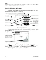
Page 24: ... different modes The first is with text area on the right side of the screen Fig 3 1 1 Charts and text area The second is with text area on the bottom line of the screen with partial information on SOG Fig 3 1 1a Charts and text windows If Target is set in the previous Fig 3 1 1a instead of the only SOG information window a text line with DST BRG XTE SOG and TTG information appears Then it is poss...

Page 25: ...EPTH GRAPH The depth graph can be shown in two different modes Depth graph dis played only on 1 3 of the screen Fig 3 1 2 The Depth Graph 1 3 of the screen or Depth graph displayed on 1 2 of the screen Fig 3 1 2a The Depth Graph 1 2 of the screen ...

Page 26: ...the left side there are histograms indicating the S N ratio SNR The bar is filled when the satellite is used for solution As example the satellite with PRN 10 is used for solution with S N 44 Azimuth 127degree and Elevation 70degree When a valid fix is received the Lat Lon Date Time Altitude VDOP HDOP SOG and COG are shown in the page 3 1 4 NAVIGATION DATA PAGE The Navigation Data page shows infor...

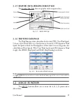
Page 27: ... on the earth AWS Apparent Wind Speed the Speed at which the Wind appears to blow relative to a moving point also called Relative Wind Speed TWA True Wind Angle and AWA Apparent Wind Angle Also SPEED Ship Speed and HEAD Ship Heading are shown Fig 3 1 6 The example of Wind Data page Note ON MAGNUM PLUS press WIND to select the Wind Data page if FUNCTION is set as WIND see Par 2 1 3 2 A B C D FUNCTI...

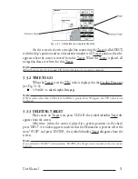
Page 28: ...r A B C D ON MAGNUM PLUS places the C and D points Fig 3 2 1 A B C D points 3 2 2 DELETING THE A B C D POINTS Place the cursor on the desired point A B C or D and press CLEAR the point is deleted When the point is deleted the cursor is placed on the previous point if existed The labels of the next points are renamed 3 2 3 NAVIGATING ON THE A B C D POINTS If fix received is good place the cursor on...

Page 29: ... TTG value is displayed in the Graphic Data page see Fig 3 1 5 PAGE to select Graphic Data page Note If SOG value is less than 1 0 knots or the BRG is greater than 90 degrees the TTG value is not displayed 3 3 3 DELETING TARGET Place cursor on Target icon press CLEAR the symbol identifies Target dis appears from the screen Otherwise when the cursor is placed in a generic position on the chart pres...

Page 30: ...ncreased Under and Over Zoom between chart levels resulting in optimal scale display for any situation Dynamic Elevation Data optimized palettes for chart plotters with 256 or more colors includes new NOAA palette for US market Perspective View Real World perspective view of the chart updated real time during navigation MAX and NT NT C CARD coexistence When NT data and MAX data cover different are...

Page 31: ... colors as similar as possible to the ones used in the original paper charts Classic uses more vivid colors Night Vision is recommended when the environment is dark in order to reduce the glare of the display The chart plotter displays maps and screen in darker colors Sunlight is designed to enhance the visibility of the screen when the chart plotter is exposed to the sunlight The maps are much br...

Page 32: ...ER On MAX charts it is possible to set the size of all names and symbols drawn on the charts selecting between Normal size the regular characters size and Large size NORMAL size LARGE size Fig 3 4 1 5 Example of Normal size on the left side and Large side on the right side settings 3 4 1 6 Dynamic Nav Aids MENU MAP SETTINGS ENTER Dynamic Nav Aids ENTER This function allows settings blinking lights...

Page 33: ...hree following options ON the Safety Status Bar is shown OFF the Safety Status Bar is not shown ICON the Safety Status Bar is not shown but a warning alarm icon is shown on the corner of the map screen as soon as any item controlled by the DSI function returns an alarm condition The Warning Icon remains displayed until the alarm condi tion persists Placing the cursor over it a quick help message i...

Page 34: ...objects Land Intertidal Depth Area Rocks Obstructions Shoreline Constructions Fish ing Facility Wrecks Dragged area Diffusion area Mooring facilities Pingos and Production installations Caution Red when Guardian Technology detects cautionary or restricted area 3 4 1 9 Currents Prediction MENU MAP SETTINGS ENTER Currents Prediction ENTER It is possible to see the variation of the Tidal arrows on th...

Page 35: ...t 10 Mt 10 Mt 10 Mt Land Elevations On Off Off Off Off On Land Elevation Data On Off Off Off Off On Roads On Off Off Off Off On POIs On Off Off Off Off On Lat Lon Grid On Off Off Off Off On Chart Boundaries On Auto Off Off Off Auto Mixing Levels On Off Off Off Off Off Value Added Data On Off Off Off Off On Chart Lock On On On On On On Und Objects Limit 9999Mt 10Mt 10Mt 10Mt 10Mt 10Mt Rocks Icon De...

Page 36: ...s Routes On Off The default setting is On MENU MAP SETTINGS ENTER Other Map Configurations ENTER Tracks Routes ENTER Depth Range Min Sets a min reference depth value The default setting is 3 Mt MENU MAP SETTINGS ENTER Other Map Configurations ENTER Depth Range Min ENTER Depth Range Max Sets a max reference depth value The default setting is 10 Mt MENU MAP SETTINGS ENTER Other Map Configurations EN...

Page 37: ...ault setting is 10 Mt MENU MAP SETTINGS ENTER Other Map Configurations ENTER Underwater Object Limit ENTER If value is set to 0 Mt the Underwater Objects are not shown on the charts Menu options are grayed out If value is more than 0 Mt i e 10 Mt in the Range from 0 Mt to the selected value the Underwater Objects are displayed according to their setting below Rocks Off Icon Icon Depth The default ...

Page 38: ...ints lines and areas The Automatic Info On Points shows information when the cursor is placed on points as Port Services Tides lights wrecks rocks buoys beacons obstruc tions land markers etc The Automatic Info On All shows information when the cursor is placed on points on lines as Depth contours Traffic Separation Territo rial Sea Cartographic Lines etc on areas Depth Built up Sea Attention Rest...

Page 39: ... for the object without icon Fig 3 4 2 1a Example of Full Info on objects with picture To see the picture press ENTER when the object with a picture is high lighted Change Picture Size When the picture is shown it is possible to fit it to screen by pressing ENTER 3 4 2 2 Quick Info on Lakes Upon viewing the chart of a lake you will click on to query the available information immediately displayed ...

Page 40: ...le information about the cartographic point under the cursor will be shown See the next paragraph 3 4 2 3 Full Info on Lakes The following is an example of Full Info on Lakes Fig 3 4 2 3 Example of Full Info page To see the Fishing object press MENU when the Fishing object is highlighted On the screen appears Fig 3 4 2 3a Example of picture associated to the Fishing object ...

Page 41: ... of the page When the selected object is a Tide Height pressing ENTER the Tide page is shown Pressing CLEAR the page is closed 3 4 4 INFO FUNCTION Place the cursor in any place you want and press MENU INFO ENTER to show the Info Tree and Expanded Info page see Par 3 5 4 3 4 5 GETTING PORT INFO Upon viewing the chart of a port or harbour you will see a Port Info icon that can be clicked on to query...

Page 42: ...fo window 3 4 6 GETTING TIDE INFO To obtain Tide Info Fig 3 4 6 Tide Info icon Place the cursor on the Tide symbol a automatic Info window is opened Fig 3 4 6a Automatic Info on Tide To display the Tide Graph page press ENTER for two times ...

Page 43: ...inding Nearest Services Port By name Port By distance Tide Stations Wrecks Obstructions Lakes info POIs 3 4 7 1 Finding Port Services To locate and display the nearest available facilities of a particular type i e the nearest Hospital sailmaker bank etc MENU FIND ENTER NEAREST SERVICES ENTER The icons of the available services are shown Use the cursor key to select any facility and press ENTER The...

Page 44: ...Finding Wrecks Searches for Nearest Wrecks MENU FIND ENTER WRECKS ENTER Use the cursor key to select the port and ZOOM IN ZOOM OUT to select next previous page Press ENTER to locate the selected Wreck on the map 3 4 7 6 Finding Obstructions Searches for Nearest Obstructions MENU FIND ENTER OBSTRUCTIONS ENTER Use the cursor key to select the port and ZOOM IN ZOOM OUT to select next previous page Pr...

Page 45: ...See the following picture Fig 3 4 7 9 Outdoor Recreational Area objects Use the cursor key to select any objects and press ENTER The list of the nearest lakes containing the facility will be shown on the screen Fig 3 4 7 9a Nearest Lakes list Thenchoosethelakeyouwantandpress ENTER theFullInfopageisshown ...

Page 46: ...48 User Manual ...

Page 47: ...R ON ENTER When Advanced Functions is Off the chart plotter operates in Basic Mode 4 1 MORE ABOUT CREATING AND USING ROUTES At anytime you may add or delete Waypoints see a route summary reverse the direction of the route or erase the entire route 4 1 1 WAYPOINTS You may add Waypoints delete Waypoints from a route move any Way point in the route to another location insert a Waypoint between two ex...

Page 48: ...g ENTER is continued to create the route until you have reached the last Waypoint your final destination Segments connecting the Waypoints are shown and the starting point is identified by a circle surrounding the first Waypoint of the route Fig 4 1 1 2 Route planning 4 1 1 3 Deleting Waypoint Select Advanced Mode Adding Waypoint or Place cursor on Waypoint Fig 4 1 1 3 Deleting Waypoint I ...

Page 49: ...s ENTER otherwise The route remains on the screen shaded until the screen is redrawn To delete route see also Par 4 1 2 2 and 4 1 2 4 4 1 1 5 Distance and Bearing to Target Once you have positioned the cursor on the desired starting Waypoint it could be the first Waypoint of the route or another one press DEST A circle surrounds the Waypoint symbol A line is shown connecting the Target with the sh...

Page 50: ...s ENTER the Target icon is moved on the next previous Waypoint in the route Otherwise in both Modes when the cursor is placed in a generic position on the chart press DEST AwindowappearstoadvicethattheDestinationpointispresent select STOP and press ENTER the symbol that identifies Target disappears from the screen but the Waypoint remains Note If you select START and press ENTER the Target icon is...

Page 51: ...Placing Waypoint between two existing ones I Press ENTER Select INSERT and press ENTER The line between the two Waypoints is turned into a dotted line move the cursor to the new position When the cursor is stationary for one second or two the line will rubber band drawing a dotted line between the last Waypoint and the cursor and another dotted line between the cursor and the next Waypoint Fig 4 1...

Page 52: ...ess ENTER Select EDIT and press ENTER to modify a Waypoint A window will be shown with Name Symbol Color and Latitude Longitude of the Waypoint advising about what Waypoint data are modifiable Fig 4 1 1 8 Edit Waypoint I Use the cursor key to select the field If you have selected Name field press ENTER use the cursor key to insert the character 8 characters max then press ENTER If Symbol field is ...

Page 53: ...out Waypoints User Points List page MENU ADVANCED SETTINGS ENTER USER POINTS ENTER Move up down the cursor key to select the User Point you wish If the page contains more than 12 User Points the list continues in the next pages Finding User Points MENU ADVANCED SETTINGS ENTER USER POINTS ENTER FIND ENTER The chart plotter exits from the User Points List page and redraws the chart The selected poin...

Page 54: ...eceive User Points Sends all User Points to an external device using the serial port MENU ADVANCED SETTINGS ENTER USER POINTS ENTER SEND Reads all User Points from NMEA Input port MENU ADVANCED SETTINGS ENTER USER POINTS ENTER RECEIVE 4 1 2 ROUTES The following functions are used for the route management The chart plot ter handles routes from 1 25 which are permanently stored in the memory as they...

Page 55: ...UTE COLOR ENTER A window is opened use the cursor keys to select the route color you want among the eight colors available Press ENTER to confirm The route appears on the screen colored by the selected color It is possible to select a different color for any route 4 1 2 5 Finding information about a route Route Report MENU ADVANCED SETTINGS ENTER ROUTE ENTER ROUTE REPORT ENTER If there are more th...

Page 56: ...route MENU ADVANCED SETTINGS ENTER ROUTE ENTER ROUTE REPORT ENTER CLEAR ENTER A window is opened select YES and press ENTER to confirm select NO and press ENTER otherwise The route remains on the screen shaded until the screen is redrawn To delete the route see also Par 4 1 1 4 and 4 1 2 2 4 1 2 6 Route Name MENU ADVANCED SETTINGS ENTER ROUTE ENTER ROUTE NAME ENTER Use the cursor key to insert the...

Page 57: ...lect Advanced Mode Adding Mark or Place cursor on Mark Press ENTER Select DELETE and press ENTER the Mark remains on the screen shaded until the next screen is redrawn Note If you try to delete a Mark that belongs to many routes the chart plotter emits three beeps and on the screen a Warning message appears If you want to delete the Mark press ENTER 4 2 1 3 Goto Place cursor on Mark Press DEST a c...

Page 58: ...awn Note If you try to move a Mark that belongs to many routes the chart plotter emits three beeps and on the screen a Warning message appears If you want to move the Mark press ENTER 4 2 1 5 Editing Mark Select Advanced Mode Adding Mark or Place cursor on Mark Press ENTER Select EDIT and press ENTER A window appears to modify Name Symbol Color and coordinates of the existing Mark Fig 4 2 1 5 Edit...

Page 59: ...r Point you wish If the page contains more than 12 User Points the list continues in the next pages See Par 4 1 1 9 4 2 1 7 Add to Route Select Advanced Mode Place cursor on Mark Press ENTER Select ADD TO ROUTE and press ENTER the se lected Mark is connected to the current route The same Mark can be added in many routes Note An existing Mark can be connected to the current route in another mode to...

Page 60: ... Press ENTER Select EDIT and press ENTER A window appears to modify Name Symbol Color of the existing Event Fig 4 2 2 4 Edit Event Use the cursor key to select the field If you have selected Name field press ENTER use the cursor key to insert the character 8 characters max then press ENTER If Symbol field is selected press ENTER a window with 16 different symbols appears Use the cursor key to sele...

Page 61: ...ppears press CLEAR to close the window and then press ENTER select the Waypoint option and press ENTER The Event is connected to the current route 4 3 EBL VRM FUNCTION EBL VRM function enables to create a dotted line and a circle respectly with direction and radius determined by the user 4 3 1 PLACING EBL VRM Select Advanced Mode ENTER EBL VRM ENTER or ON MAGNUM PLUS EBL VRM if it is present On th...

Page 62: ...lace the cursor on the desired position and ON MAGNUM PRO press ENTER on the screen the Create window appears by using the cursor key select A B C D and press ENTER ON MAGNUM PLUS press A B C D The A point and an information window on A appear Move the cursor and ON MAGNUM PRO press ENTER select A B C D and press ENTER again ON MAGNUM PLUS press A B C D the B point appears connected to A with a st...

Page 63: ...lacing cursor on the segment connecting two points the information win dow appears Select INSERT and press ENTER by the cursor key move the cursor on the screen a dotted line appears By pressing ENTER the new point is placing between the two existed points which are renamed 4 4 6 NAVIGATING ON THE A B C D POINTS If fix received is good place the cursor on the desired point A B C or D and press DES...

Page 64: ... ENTER 4 5 5 DELETING TRACK MENU ADVANCED SETTINGS ENTER TRACK ENTER DIS TANCE ENTER Deletes all track After pressing ENTER a warning window appears select Yes and press ENTER to confirm select No otherwise 4 5 6 DELETING SELECTED TRACK MENU ADVANCED SETTINGS ENTER TRACK ENTER DELETE SELECTION ENTER Deletes the track selected After pressing ENTER a window appears press ENTER to set the first point...

Page 65: ...Nm the distance unit is selected by the user see Cap 5 The default setting is 0 01 Nm 4 5 9 SELECTING TIME MENU ADVANCEDSETTINGS ENTER TRACK ENTER TIME ENTER When the tracking function is On and the type of track storing is Time the chart plotter can store a fix after a defined time Choose among 1 5 10 30 sec 1 5 10 min The default setting is 1 sec 4 6 USER C CARD MENU The chart plotter allows to ...

Page 66: ...usedinfilenames however theytakeupseveralcharacters leaving you with little flexibility The secret is to find a compromise a point where you can combine a date with a word creating a unique filename The maximum length of the filename is 8 characters The characters may be numbers 0 9 letters A Z and spaces for example legal identifiers are ABC AA 12121212 A B C 1 A 1 and so on Press CLEAR On the sc...

Page 67: ...NU ADVANCED SETTINGS ENTER USER C CARD ENTER CHANGE ENTER Allows to change the User C CARD 4 7 C LINK C Link system is a feature which allows to sharing the same cartographic data between two chart plotter units CP linked via serial I O port In order to activate C Link function a MAX data C CARD called REGU LAR C CARD must be inserted into one of the two chart plotters and a special MAX data C CAR...

Page 68: ...ata will be continuously sent to the Slave until the navigation is active If the Master is navigating to a Single Destination the Slave will show the Destina tion position and activate the navigation to it If the Master is navigating to a Route the Slave will show the Route Leg composed by the Destination and the Waypoint after the Destination Next Way point and activate the navigation to it Any v...

Page 69: ...e sent only for Route Following navigation The Destination Icon Navigation leg Fix Position to Destination the Next Waypoint Icon and all other relevant C Link navigation data will be shown on the Slave chart plotter Any variation of the C Link navigation data on the Master will be communicated to the Slave so to keep data aligned on both devices 4 8 1 2 C Link serial connection The two chart plot...

Page 70: ...n Slave mode is set the chart plotter cannot manipulate the C Link navigation data anymore Stop current navigation If the navigation was already active it will be disabled as soon as Slave mode is set An appropriate warning message will be shown to notify that the Navigation is already active and to confirm whether Slave mode can be set Inhibit Navigation operation As soon as Slave mode is set the...

Page 71: ... the infor mation received and executes the relative actions depending on its current working status Important When the Navigation to the external Destination is activated the Slave Chart Plotter will show all relevant C Link navigation data exactly like when the destination is not the external one Destination Name DST and BRG to Destination calculate XTE calculate TTG etc These values will be dis...

Page 72: ... Calculated Distance to Next Wpt Distance to travel from ship to the Wpt after the Des tination calculated Distance to Dest Next Route Leg length Distance to Last Wpt Distance to travel from ship to the End of the Route Calculated Distance to Dest Distance From Dest to last Wpt received from PCMPN 1 TTG To Destination Estimated Time to travel the Distance to Last Wptt Calculated using Cruising Spe...

Page 73: ...ormation from the ship automatically requiring a minimum of involvement of ship s personnel and should have a high level of availability AIS transponders in stalled on IMO vessels use VHF frequencies to Transmit details of their own vessel Receive details from other vessels or navigation aids within VHF range Information being transmitted from vessels over 300 tons that due to recent worldwide leg...

Page 74: ...is the time remaining before the CPA is reached TCPA Alarm Occurs if TCPA is less or equal to TCPA Limit This test is done for active targets only and if CPA value is less or equal to CPA Limit Radio Call Sign International call sign assigned to vessel often used on voice radio Name Name of ship 20 characters MMSI Maritime Mobile Service Identity MMSI number A unique 9 digit number that is assigne...

Page 75: ...0 minutes The maximum number of tracked targets is 100 Depending on the scale the presentation of the targets change to remove clutter on the screen This information is updated every 3 seconds to 6 minutes depending on speed and rate of turn enabling the track of the vessels in range to be plotted Fig 4 9 1 AIS Symbols 4 9 2 AIS MENU To configure the chart plotter to receive AIS data follow the pr...

Page 76: ...NTER TCPA LIMIT ENTER The values allowed are from 1 to 30 min The default setting is 10 min 4 9 3 TO SET THE CHART PLOTTER FOR RECEIVING AIS Make sure that the AIS receiver is properly connected to the chart plotter The chart plotter reads the AIS NMEA message VMD type 1 2 3 and 5 Select the used serial port and transmission speed by following the proce dure MENU BASIC SETTINGS ENTER INPUT OUTPUT ...

Page 77: ...ervice is an innovative meteorological forecasting system with the ability to visualize the weather forecast overlaying it on cartography The weather data is held on C MAP s weather server which can be accessed via a C COM modem con nected to the chart plotter or by using the C MAP personal Suite or the DPS Dealer Programming System saving the weather data on a User C CARD The weather data are ove...

Page 78: ...etotheC MAPweatherserverandtodownload C MAP weather data directly via C COM Select Country to Call Allows the selection of the country to call The whole telephone number set is automatically updated after every download SIM PIN Allows inserting of the PIN of the SIM Download Area Allows the weather download a squared grey area where the weather data will be downloaded is centered on cursor positio...

Page 79: ...the normal panning function Zoom In Out Zoom in out functions are allowed as usual by using ZOOM IN ZOOM OUT Set Date and Time ENTER to modify date and time values Layer Selection PAGE to cycle the weather layers Exit CLEAR to close the weather prediction page 4 11 1 4 Real Time View MENU C WEATHER ENTER REAL TIME VIEW ENTER The following selections are available Real Time View On The data is show...

Page 80: ...e displaying on the screen are shown in the following table Position Request icon Distress Call icon P D Fig 4 12 Distress Call and Position Request icons Note The label can be the MMSI or the corresponding vessel s name If in the DSC Directory the MMSI has been associated to its relative vessel name the vessel s name is shown in the label instead of the MMSI 4 12 1 DISTRESS CALL AND POSITION REQU...

Page 81: ...on View Exits the pop up screen and remains on the selected map screen 4 12 2 DSC MENU To select the DSC menu MENU DSC ENTER TheDSCmenuisshownonthescreen theitemsaredescribedinthefollowing paragraphs 4 12 2 1 DSC LOG MENU DSC ENTER LOG ENTER Selecting Log shows the Distress Call Log page or Position Request Log page it depends which of the two was selected 03 03 01 08 31 PM 33 30 505 N 118 18 529 ...

Page 82: ... ENTER Selects the DSC Directory page From this page the user can assign the Ves sel Name Contact Name and Phone number to any MMSI Maritime Mobile Service Identity so that when a DSC Distress Call or Position Request is received the name of the vessel is displayed in place of the MMSI number a unique number that is assigned to a DSC radio station for use in emergency situations STRIKE 99 00366124...

Page 83: ...ition Date and Time Distance and Bearing from current vessel s position Pressing ENTER it is possible by selecting DELETE deletes the DSC icon from the DSC Log page otherwise by selecting DSC LOG the DSC Log page is shown 4 13 FISH FINDER MENU The chart plotter combined with the sonar performance of the Fish Finder is one of the most advanced marine navigation system available MENU FISH FINDER SET...

Page 84: ...cludes the Radar antenna transmitter receiver and necessary electronics The scan ner unit is connected to a chart plotter equipped with software capable of displaying the Radar functions MENU RADAR SETUP ENTER ONLY ON MAGNUM PLUS RADAR for 1 second To select the Radar pages PAGE cursr keys ENTER to select the desired Radar page ONLY ON MAGNUM PLUS RADAR For more information see the specific User M...

Page 85: ...them see Par 3 2 in Advanced Mode it is possible to place move navigate and delete them see Par 4 4 About page Selects a page that gives information on software and cartography version and general software specifi cation as user points number routes number and so on For more information see Par 1 3 MENU About ENTER Activate Simulation Enables On or disables Off the Simulation mode The default sett...

Page 86: ...is Ft MENU BASIC SETTINGS ENTER ALTITUDE ENTER Anchor Alarm This function allows inserting of the limit of anchor dragging beyond that the alarm is activated The chart plotter computes the distance between the current GPS position and the GPS position saved at the activationoftheanchoralarminthemenu Ifthecomputeddistanceexceedsthevaluesetinthemenu the chart plotter shows the alarm message and star...

Page 87: ...avigation Bearings Selects either degrees Mag or True If magnetic readings are selected the variation is computed auto matically for every zone as soon as the chart is displayed The default setting is Mag MENU ADVANCEDSETTINGS ENTER COMPASS ENTER BEARINGS ENTER Beeper Turns On Off the sound after pressing a key beep The default setting is On MENU ADVANCED SETTINGS ENTER SETUP ENTER BEEPER ENTER BR...

Page 88: ...Chart Bounda ries ENTER Chart Lock When Chart Lock is On the available zoom scales are only the ones containing cartographic data Instead when Chart Lock is Off it is possible to zoom down into zoom scales not covered by carto graphic data after the last available zoom scale covered by cartographic data The DSI window if present will show NO CHART when an empty level is entered in the location of ...

Page 89: ...rse Vector course is given by the value of COG Course Over Ground and its length is propor tional to the SOG Speed Over Ground This option disables Off or sets time as 2 10 30 min 1 2 hours Infinite The default setting is Infinite MENU BASIC SETTINGS ENTER COURSE VECTOR ENTER Cross Track error XTE The distance from the ship s present position to the closest point on a line between the origin and d...

Page 90: ...models are called Datum or Coordinate Systems There are many different Datum in use each one gives different Lat Lon positions for an identical point on the surface of the earth Dead Reckoning Enables On or disables Off0 the Dead Reckoning The default setting is Off MENU ADVANCED SETTINGS ENTER FIX ENTER DEAD RECKONING ENTER Default Indicates a value or a setting which is used if the user has not ...

Page 91: ...nly Depth Contours Imaginary lines connecting points of equal water depth Depth Graph 1 2 screen Selects the Depth Graph displaying on 1 2 of the screen PAGE Fig 5 The Depth Graph 1 2 screen Depth Graph 1 3 screen Selects the Depth Graph displaying on 1 3 of the screen PAGE Fig 5a The Depth Graph 1 3 screen Depth Range Min Sets a min reference depth value The default setting is 3 Mt MENU MAP SETTI...

Page 92: ... setting is Custom MENU MAP SETTINGS ENTER Other Map Configurations ENTER Display Mode ENTER Distance Track When the tracking function is On and the type of track storing is Distance you can store a fix when the distance from its last stored position is greater than a defined distance Choose in the range 0 01 0 05 0 1 0 5 1 0 2 0 5 0 10 0 Nm the distance unit is selected by the user The default se...

Page 93: ...moves to the new point The default setting is Off MENU ADVANCEDSETTINGS ENTER SETUP ENTER EXTERNWPT ENTER File It is a collection of information of the same type stored on a User C CARD Each file must have a unique name ideally one that describes its contents Filenames are kept in a directory on each User C CARD see Par 4 6 Filter Dump Sets the Filter step Move cursor key up down to insert value i...

Page 94: ...1 1 4 and 4 2 1 3 DEST GPS Global Positioning System It is a satellite based navigation system operated by the US Department of Defense It gives the naviga tor a position 24 hours a day 365 days a year under any weather conditions GPS Cable Wiring Displays the Cable Wiring page for GPS MENU BASIC SETTINGS ENTER INPUT OUTPUT ENTER GPS CABLE WIR ING ENTER GPS Data Page The GPS Data Page shows in gra...

Page 95: ...GALARM ENTER Note The Grounding Alarm function only operates with the new C CARDs It also affects the speed of the redraw of the screen If this function is not used it maybe disabled Grounding Alarm Range Allows setting the length of the sector to be detected among 0 25 0 5 1 0 Nm The default setting is 0 25 Nm When any of the searched objects is found in the scanned area a tick marker is printed ...

Page 96: ...ree s items The upper side of the page contains the Info Tree and the Lower side contains the expanded informa tion WhilemovingthecursorthroughtheInfoTree alltherelevantinformationoftheselectedobject is shown on the lower part of the page MENU INFO ENTER Input Output menu Selects the proper format Port1 2 3 4 5 Input Port1 2 3 4 5 Output Port1 2 3 4 5 Output Sen tences Displays also the Power I O ...

Page 97: ...phic meridians at any place expressed in degrees West or East to indicate the direction of magnetic North from true North It changes from point to point and at the same point with time Map Datum Selects the Map Datum WGS 1984 is the default Map Datum MENU ADVANCED SETTINGS ENTER NAVIGATE ENTER MAP DATUM ENTER Map Orientation Selects the orientation of your chart according to North the map is shown...

Page 98: ...n the screen the MOB symbol and a window to advise that the MOB is activated appear press CLEAR to delete this window Data displayed in Text Area are related to MOB Placing the cursor on the MOB symbol an information window appears Fig 5e Man Overboard Note Intheinformationwindowthebottomside ENTERforOptions appearsonlyif the Advanced Functions item in the Basic Settings menu is activated On Delet...

Page 99: ...DS PRESENTATION ENTER Navigate menu Selects the desired setting for Orientation Resolution Coordinate System Map Datum Fix Datum and Roll Road Scale Enable the Reset Total Trip and Reset Partial Trip functions MENU ADVANCED SETTINGS ENTER NAVIGATE ENTER Navigate mode In Operating mode called also Home mode all operations refer to the ship s position Enter Navigate CLEAR Exit from Navigate move the...

Page 100: ...t Britain A coordinate system describing only Great Britain Generally used with GBR36 datum which also describes only Great Britain This coordinate system cannot be used in any other part of the world MENU ADVANCED SETTINGS ENTER NAVIGATE ENTER COORDINATE SYSTEM ENTER OSGB ENTER Other Map Configurations menu This function allows the user to customize the following selections and is divided into th...

Page 101: ...e View ENTER Pictures and Diagrams The MAX data format allows assigning one or more image to any cartographic object These Pictures are typically used to facilitate the identification of cartographic objects or places around the map they can be the landscape layout nearby a harbor the shape of a bridge or of a buoy etc On some objects such as bridges the image associated can represent the Diagram ...

Page 102: ...a new presentation software which displays special Port Facility Symbols see Par 3 5 3 Ports Services TurnsOn OffthedisplayingofPortsandServices areasalongshorewithfacilitiesformooring down loading and uploading of ships generally sheltered from waves and winds Port installations are piers wharves pontoons dry docks cranes The default setting is On MENU MAP SETTINGS ENTER Other Map Configurations ...

Page 103: ...TINGS ENTER NAVIGATE ENTER ROLLROADSCALE ENTER Route Sequence of Waypoints connected by segments Among the available routes only one is the active route which is shown by a straight line and arrows to indicate the direction The first Waypoint of the active route is surrounded by a circle see Par 4 1 2 MENU ADVANCED SETTINGS ENTER ROUTE ENTER Route menu Allows route management Selecting Route MENU ...

Page 104: ...ENTER Seabed Type Enables On or disables Off the displaying of the Seabed Type MENU MAP SETTINGS ENTER Other Map Configurations ENTER Seabed Type ENTER Send Receive Marks Routes Sets the desired port used for transferring User Points and Routes functions MENU BASICSETTINGS ENTER INPUT OUTPUT ENTER SEND RECROUTES MARKS ENTER Port1 Port2 Port3 Port4 Port5 ENTER Send Route Transmits the Active Route ...

Page 105: ...r can store a fix when the distance from its last stored position is greater than a defined distance Time the chart plotter can store a fix after a defined time Auto the software decides when storing a position on the basis of the straight or curved track The default setting is Time MENU ADVANCED SETTINGS ENTER TRACK ENTER STEP UNIT ENTER STR Steering The difference between COG and CTS If COG is 2...

Page 106: ...ondSymbolforeveryPortortide pointinthedatabasecoveredbythatparticularC CARD Tide Stations Finds the nearest Tide Stations up to 10 on the map from the boat position if a valid fix is received or from the cursor position if the fix position is not good MENU FIND ENTER TIDE STATIONS ENTER Tides Currents Turns On Off the displaying of Tides and Currents The default setting is On MENU MAP SETTINGS ENT...

Page 107: ...stored position is greater than a defined distance or after a defined time A line connects such points and represents the past course called the track of the ship see Par 4 5 Active Track selecting MENU ADVANCED SETTINGS ENTER TRACK ENTER ACTIVE TRK ENTER Track storing ON OFF MENU ADVANCED SETTINGS ENTER TRACK ENTER TRACKING ENTER Visible ON OFF MENU ADVANCED SETTINGS ENTER TRACK ENTER VIS IBLE EN...

Page 108: ... List Displays the User Points List page on the screen see Par 4 1 1 8 MENU ADVANCED SETTINGS ENTER USER POINTS ENTER UTC Universal Time Coordinated A time scale based on the rotation of the earth that is used by most broadcast time services UTM Universal Transverse Mercator Metric Grid system used on most large and intermediate scale land topographic charts and maps MENU ADVANCED SETTINGS ENTER N...

Page 109: ...cursoronrouteleg ENTER INSERT ENTER move cursor ENTER Finding Waypoint MENU ADVANCED SETTINGS ENTER USER POINTS ENTER FIND ENTER WGS 84 World Geodetic System 1984 Coordinate System or Datum developed by the Defense Mapping Agency DMA Wind Data page Selects the Wind Data page PAGE Fig 5i The Wind Data page Wind Speed unit Selects the Wind Speed unit among Kts Knots m s and Kmh kilometers per hour T...

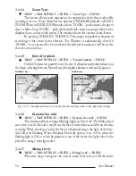
Page 110: ...a wider but less detailed view Compresses map scale scale value is refreshed When Plotter Mode option is set On from the map configuration setup it allows zooming into map scales not covered by cartographic details Pressing and holding ZOOM OUT allows fast zoom function Zoom Type This feature allows more expansions or compression of the chart scale while zooming in or out MENU MAP SETTINGS ENTER Z...

Page 111: ... selectable Cartography C MAP C CARD Operating temperature range 0 55 degrees Celsius Memory Non volatile with battery back up Keyboard Silicon rubber backlight Weight 600 gr Accessories External Bracket kit 2 Fuses 1 Amp fuseholder I O cable CBC0FS0603 AUX IN I O cable 1 5 mt 5 9 Power supply and I O CBC0FS0804 Video Cable CBCHMS0700 User Manual Quick Reference Guide Dimensions mm inch 140 5 5 17...

Page 112: ...OUTPUT 3 INPUT 3 GND SIGNAL RETURN 1 2 3 4 5 6 RED GREEN BROWN NC NC BLACK YELLOW SHIELD WIRE COLOR FUNCTION 1 GND 2 VCC 3 R 4 G 5 B 6 HSYNC 7 VSYNC 8 N C 9 BRIGHTNESS CONTROL PIN FUNCTION VIDEO OUTPUT VIDEO OUTPUT GND COMMON POWER OUTPUT 10 35 Vdc INPUT 4 INPUT 4 OUTPUT 5 OUTPUT 4 INPUT 5 EXTERNAL ALARM OUTPUT AUX IN I O CABLE AUX IN I O CABLE BLACK RED WHITE GREEN GRAY YELLOW BROWN BLUE PIN 1 2 ...

Page 113: ...115 User Manual 6 4 TYPICAL CONNECTIONS POWER I O Connector 6 4 1 GPS CONNECTIONS GPS on Port 1 GPS on Port 2 GPS on Port 3 6 4 2 AUTOPILOT CONNECTIONS Autopilot on Port 1 ...

Page 114: ...116 User Manual Autopilot on Port 2 6 4 3 EXTERNAL NMEA CONNECTIONS External NMEA on Port 1 External NMEA on Port 2 6 4 4 C COM CONNECTION ...

Page 115: ...ware Library version and date SYSTEM TEST XXXX V x yy NTSL V x yy zz R gg mm yyyy RAM menu Dim menu Cartridges Serial ports Modem Test EXTERNAL ALARM Fig 6 5 System Test Use the cursor key to select the desired test this will display in reverse video and with the relative menu window To choice the test press ENTER To exit from any submenu press CLEAR To exit from the System Test turn Off the chart...

Page 116: ...tness instead of to left it will increase brightness 6 5 3 CARTRIDGES To check the C CARD and its connector Background ROM To test the WorldWideBackground If there is not a malfunction the code of the Background and the message OK are shown but if the Background is defective the message Faulty is shown C CARD Test To test the C CARD There are the possible situations 1 if there is a C CARD inserted...

Page 117: ...plotter to act as a computer terminal and display the incoming data exactly as it received If the data displayed on the screen is unrecognizable you may have selected the wrong input parameters for your particular receiver Check your receiver manual to be sure that you have selected the proper inter face format If the screen is blank you may have a broken connection and no data is being received U...

Page 118: ... restart the unit now If the display will not be visible shut off the chart plotter again then power it up keeping pressed ZOOM IN to set default resolution 640x480 Choosing YES the chart plotter will be restarted and the new settings applied Choosing NO the new settings will be applied only next time the chart plotter is powered up Choosing ABORT will dis carded all changes and nothing will be ap...

Page 119: ... no metal obstacle is placed around the chart plotter acting as a shield for the antenna If after 15 minutes the chart plotter does not get the fix turn it Off and On again THE CHART PLOTTER DOES NOT TURN OFF If after a POWER pressure for at least 3 seconds the chart plotter does not turn Off then turn Off the voltage THECHARTPLOTTERDOESNOTRESPONDTOANYCOMMAND Try to turn Off and then turn On If th...

Page 120: ... Basic Mode 49 89 Basic Settings 89 106 Beacon 89 Bearing 89 Beep 12 18 Beeper 89 BRG 89 Buoy 89 Buoys ID 37 BWC 95 C C CARD 22 90 95 110 118 C CARD Connector 118 C CARD Test 118 C COM 21 116 C COM Connections 21 116 C Link 69 90 C Staff 79 C Voice 92 C Weather Service 92 Cartography 113 Cartridge 22 110 118 Caution Notice 18 Chain 87 90 102 Change User C CARD 69 90 Change Parameters 119 Changing ...

Page 121: ...tive Calling 82 DIM Menu 118 Dimensions 113 Display 101 102 Display Mode 32 39 94 Display Resolution 113 119 Display Settings 119 Displaying Track 66 Distance 67 Distance Track 94 Distance Unit 94 Distance and Bearing to Target 51 Distance To Go 94 Distress Call 82 94 DSC 82 94 DSC Directory 84 DSC menu 83 DTG 94 Dynamic Nav Aids 34 94 E EBL 63 94 EBL VRM Placing 63 Echosounder 94 Editing EBL VRM ...

Page 122: ...enu 98 103 104 Inserting A B C D 30 64 Inserting C CARD 22 Inserting MOB 100 Inserting Target 107 Inserting Waypoint 53 111 Interface 113 Inverting Route 106 K Key 12 Keyboard 113 L Lakes By Name 46 98 Lakes Info 98 Lakes Information 46 98 Land Elevation 98 Land Elevation Values 38 98 Landmarks 38 98 Language 18 98 102 Lat Lon Grid 39 99 Latitude 99 Light Sectors 37 101 List User Points 62 List Us...

Page 123: ...sumption 113 Power I O Cable Wiring 104 Power On 18 Q Quick Info 41 85 Quick Info on Lakes 41 R Radar 86 RAM Clear 118 RAM Menu 117 RAM Test 117 Receive Route 104 106 Receive User Points 104 106 Receiver 19 Removing C CARD 23 Reset Partial Trip 104 Reset Total Trip 105 Resolution 113 119 Reversing Route 57 58 105 Rivers Lakes 38 Roads 38 98 103 105 110 Rocks 39 105 111 Rolling Road 29 Rolling Road...

Page 124: ...ing type 66 Track storing 66 109 Tracking 109 Tracks Routes 38 109 TRN 109 Trouble shooting 121 TTG 31 52 109 Turning 109 Turning Off 18 Type of Data 81 Typical Connections 115 U Underwater Objects 110 Underwater Objects Limit 39 110 Unit 88 Universal Time Coordinated 110 User C CARD 22 67 95 110 User C CARD Menu 67 User Point 110 User Point Name 110 User Points List 110 User Points List page 55 6...

Reviews: