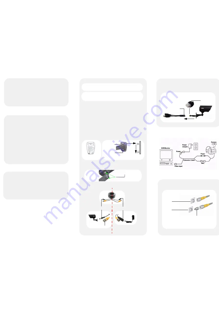
To install the camera:
1. Apply the mounting template sticker to the desired
mounting location (Figure 1).
2. Drill the holes according to the template, and push the
wall plugs into the holes.
3. Fasten the four screws 3/4 of the way.
4. Place bracket onto the screws (step 1) and gently lower
the bracket so that the screw locks the bracket in place
(step 2) (Figure 2).
5. Fasten the screws until they are secure.
6. Set the position and angle of the camera using the
provided Allen key.
7. Connect the extension cable to the camera:
ATTENTION
- Ensure there is an opening in your mounting surface large
enough for the cables to pass through. If necessary, you can run the cables
through the pass-through ports at the top or bottom of the stand.
ATTENTION
-
Test all connections and ensure the camera is working
correctly prior to permanent installation.
Mounting Surface
Template Sticker
(Figure 1)
(Figure 2)
Step 1
Step 2
Top pass-
through port
Bottom pass-
through port
Connect the BNC and
power connectors to the
camera.
Connect the BNC connector to the
video input of the monitor/DVR,
and connect the included power
connector to a power adapter.
Male power connector
Female power connector
BNC Connector
To Camera
To Monitor/ DVR
Contents
Features
•
Ultra High Resolution image sensor produces 540 TV
lines of resolution
•
Advanced noise reduction improves image quality and
recording storage efficiency
•
Intelligent IR technology prevents image overexposure
•
Capable of viewing images up to 130ft (40m)* away in
total darkness with IR night vision
•
6mm lens captures far away objects
•
Cable pass-through wall mount bracket protects the
connection cable from vandalism
•
IP67 rated housing for indoor / outdoor installations**
* IR illumination range under ideal conditions. Objects at or beyond this
range may be partially or completely obscured, depending on the camera
application.
** Not recommended for submersion in water
•
Camera with cable pass through wall bracket
•
Sunshade
•
66 ft. BNC/Power Extension Cable
•
BNC to RCA Adapter
•
12V DC Power Adapter
•
4x Mounting screws
•
4x Wall plugs
•
1x Allen key
•
1x Mounting template
Installation Tips
•
Point the camera towards a direction where there is
the least amount of obstructions (i.e. tree branches).
•
Install the camera in a location that is difficult for
vandals to reach.
•
Secure cabling so that it is not exposed or easily cut.
•
Connect your system and cameras to a back-up power
supply. This ensures the system continues to record
during power outtages.
Installing The Camera
Warning / Caution Statements
1.
Read this guide carefully and keep it for future reference.
2.
Follow all instructions for safe use of the product.
3.
Use the camera within given temperature, humidity and voltage levels noted
in Camera Specifications.
4.
Do not disassemble the camera.
5.
Do not point the camera directly towards the sun or a source of intense light.
6.
Use only the supplied regulated power supply. Use of a non-regulated, non-
conforming power supply can damage this product and voids the warranty.
7.
The supplied extension cable is rated for surface mounting only.
Cables for in-wall / floor-to-floor installations are sold separately.
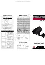
Setup Diagram
DVR/CCTV MONITOR
Video IN
TV/VCR
Video IN
Attach the included BNC to RCA adapter to connect the
extension cable to RCA inputs (i.e. for a TV connection).
Accessories
BNC to RCA Adapter
(included)
BNC to RCA Adapter
Connecting the Pin Connector
Pin Connector
BNC/Power connector
If the pin connection becomes loose, simply re-connect the pin
connector to the BNC/power connector. Line up the notch on
the pin connector with the arrow on the BNC/Power connector,
and push the connectors together. The pin connector goes in
one way only.
Notch
Arrow
All manuals and user guides at all-guides.com


