Camera Switches
iii
Camera Switches
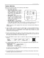
Please set the Camera Switches prior to powering on the Camera.
①
Function Selection Switches:
AUTO IRIS LENS Switch
– Set the
switch to either the “DC” or “VIDEO”
position, depending on the type of
lens attached to the camera. Set the
switch to “DC” for the supplied lens, or
any non AI lens types.
EE/AI Switch
– When using an Auto
Iris Lens on the camera, set the
switch to the “AI” position. Set the
switch to “EE” for other lens types,
including the supplied lens.
BLC/OFF Switch
– If the camera is
directed towards a backlight, objects
in the image may appear dark. Set the switch to the “BLC” position to turn on the
Backlight Compensation, and improve the image quality in backlight conditions.
NOTE
: This camera is NOT supplied with an Auto Iris lens. The default Switch Settings are:
DC, EE & BLC
②
Video Out (BNC): Connect the camera to a BNC Cable, or to the provided BNC Extension
cable to transmit video to a receiver, such as a DVR, Observation System, TV or other
similar viewing device. The included BNC to RCA Adaptor may be needed for proper
connection to your viewing device.
③
Power Connector Block: This camera can be powered using either 12V DC or 24V AC
power, and has a removable 12V DC Power Cable. To use 24V AC Power, remove the 12V
DC Cable, and connect directly to a 24V AC Power source.
④
AUTO IRIS LENS Connector: Used to connect the cable from the Auto Iris lens to the
Camera.
1 2 3 4
DC TYPE
DAMPING- DRIVE+
DRIVE-
VIDEO TYPE
DC 9V
N.C
IRIS SIGNAL
GND
⑤
DC LEVEL Brightness Adjustment: The DC Level adjustment controls the brightness of the
connected Auto Iris Lens.
Monitor picture
Adjustment direction
Brighten the Image
Turn clockwise
Darken the Image
Turn counterclockwise
To use this control, the camera must have a connected Auto Iris lens, and the switches must
be set to the “AI” & “DC” positions.
⑥
Power ON/OFF LED: The LED displays the ON or OFF status of the camera. The LED will
illuminate in green when the camera is ON.
1
2
3
4
Summary of Contents for CVC8001
Page 7: ...Notes vii Notes...


