10
Super DNR High Resolution Color Camera
Super DNR High Resolution Color Camera
11
■
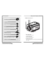
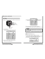
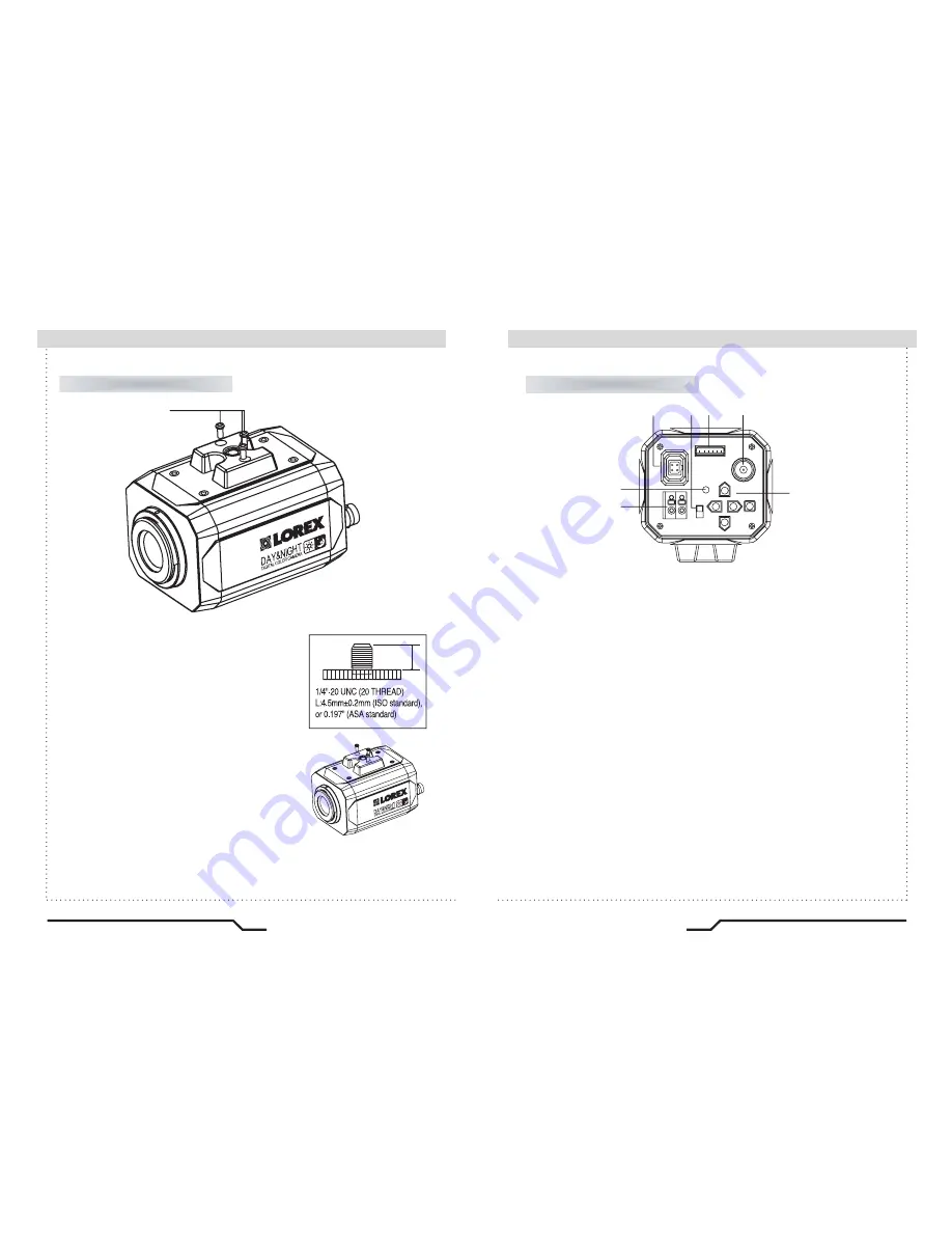
Names and Functions of Parts
Names and Functions of Parts
■
IRIS JACKOSD EXTRA
POWER
DC
VIDEO
SET
VIDEO OUT
AC24V IN
DC12V IN
⑪
⑤
⑥ ⑦
⑧
⑨
⑩
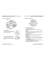
Rear
⑤
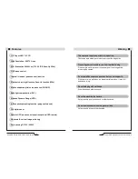
Auto iris lens connector
Connection terminal for an auto iris lens.
⑥
Auto iris lens selection switch
Used to change between DC or Video depending upon the type of auto
iris in use.
⑦
OSD Extra
Connect to remote controller (optional
-
model # ACCRC01) to do camera
set up from the ground instead of on the ladder. Also includes BNC spot
video out to connect to a service monitor.
⑧
Video output terminal
Sends video signals and connects to the video input terminal of the monitor.
⑨
Power lamp
Lights up when the correct power is supplied to the camera.
⑩
Setting button
●
SET button
: Used for the menu display. This button can be used to
confirm settings after changing the value of the selected function or
current conditions.
●
UP & DOWN buttons
: Used for selecting items by moving the cursor
up or down on the menu screen.
●
LEFT & RIGHT buttons
: Used when changing item values, by moving
the cursor to the left or right on the menu screen.
⑪
Power input terminal
Low voltage power connection.
Top
④
Mounting Bracket
Use the screw holes provided when fixing the
camera onto a mounting bracket. Use the clamp
screw as shown in the picture.
※
The mounting bracket can be attached to either
the bottom or the top of the camera.
Be careful not to tighten the screws more than
5mm into the body, otherwise serious damage
can occur.
L
④
Summary of Contents for CVC8011
Page 22: ...MEMO...

