background image

Controlling the PTZ camera with an
NVR

5

The camera can accept PTZ commands directly through the Ethernet cable. There is no need to
run special wiring to control the movement of the PTZ camera.

For instructions on controlling the PTZ camera with the N882 Series NVRs, see 6

Controlling

the PTZ camera with N882 Series NVR

page 18

For instructions on controlling the PTZ camera with the N842/N862 Series NVRs, see 7

Con-

trolling the PTZ camera with N842/N862 Series NVRs

, page 23

#LX400116; r. 1.0/57307/57307; en-US

17

Summary of Contents for E881AP Series

Page 1: ...Instruction Manual E881AP Series ...

Page 2: ......

Page 3: ...Instruction Manual E881AP Series LX400116 r 1 0 57307 57307 en US iii ...

Page 4: ... QUALIFIED SERVICE PERSONNEL The lightning flash with arrowhead symbol within an equilateral triangle is intended to alert the user to the presence of uninsulated dangerous voltage within the product s enclosure that may be of sufficient magnitude to constitute a risk of electric shock The exclamation point within an equilateral triangle is intended to alert the user to the presence of important o...

Page 5: ...trolling the PTZ camera with N882 Series NVR 18 6 1 Controlling the PTZ Camera 18 6 2 Advanced PTZ Controls 19 6 2 1 Presets 20 6 2 2 Tours 20 6 2 3 Pattern 21 6 2 4 Auto Scan 21 7 Controlling the PTZ camera with N842 N862 Series NVRs 23 7 1 Controlling the PTZ Camera 23 7 2 Advanced PTZ Controls 24 7 2 1 Presets 25 7 2 2 Tours 26 7 2 3 Pattern 27 7 2 4 Auto Scan 28 8 Inserting the microSD Card Op...

Page 6: ......

Page 7: ... chemicals such as acetone can permanently damage the plastic Do not disassemble the camera Do not point the camera directly towards the sun or a source of intense light Make sure to secure the camera during installation by connecting the included safety chain Mount the camera in an area that is visible but out of reach Make sure to install the camera in a location that can support the combined we...

Page 8: ...crews flat washers x4 ESD Gloves Safety Chain Waterproof Tape Waterproof Connector Allen Key A Allen Key B M6x14 Screws x3 Rubber Ring NOTE Your accessories might appear different from the ones depicted in this guide The following are user supplied tools not included You will need use LX400116 r 1 0 57307 57307 en US 2 ...

Page 9: ...Getting Started 2 Drill Screwdriver LX400116 r 1 0 57307 57307 en US 3 ...

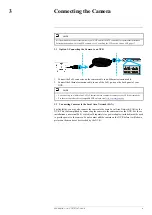
Page 10: ...OTE You can use up to a 300ft 91m CAT5e Ethernet cable to connect the camera to your NVR not included For the most up to date list of compatible NVRs please visit lorex com compatibility 3 2 Connecting Cameras to the Local Area Network LAN For flexibility you may also connect the camera to the same Local Area Network LAN as the NVR This is accomplished by connecting the camera to the same router a...

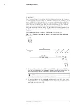
Page 11: ... compatible NVR or a PoE switch on the same network as the NVR PoE switches are available for purchase on lorex com Complete the following steps to connect the camera to the NVR over the LAN Step 1 of 2 Option A Connecting the camera to your local network using an optional PoE switch 1 Connect an Ethernet cable of up to 300ft 91m rated CAT5e or higher not included from the LAN port on an external ...

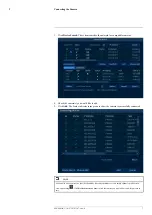
Page 12: ...l and model number of your recorder visit www lorextechnology com and search for Where is the Serial and Model Number located 3 3 Adding the PTZ Camera to an NVR The following instructions are based on the N842 N862 Series NVRs See your NVR s instruc tion manual for instructions on controlling the PTZ camera with your system NOTE You must have at least one empty channel before attempting to add th...

Page 13: ...5 Click Add The Status indicator turns green to show the camera is successfully connected NOTE You can also add a camera to a specific channel by hovering the mouse over an empty channel in split screen view and clicking Click Device Search and double click the camera you would like to add Right click to exit LX400116 r 1 0 57307 57307 en US 7 ...

Page 14: ...ing is not exposed or easily cut Mount the camera in an area that is visible but out of reach NOTE This camera includes all components required for wall mounting For the most up to date software and complete instruction manuals 1 Visit lorex com 2 Search for the model number of your product 3 Click on your product in the search results 4 Click on the Downloads tab 4 2 Installation Indoor Outdoor C...

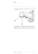
Page 15: ...ten all the way 3 Use the included wall mount to mark holes for the mounting anchors x4 and cables 4 Drill holes drill bit size 3 8 to a depth of 2 8 70mm in the mounting surface where marked 5 Insert the mounting anchors x4 into the holes and tap them into the wall with a hammer LX400116 r 1 0 57307 57307 en US 9 ...

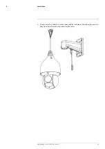
Page 16: ...Installation 4 6 Connect the safety chain between the camera and the wall mount This allows the camera to hang from the wall mount while connecting the cables LX400116 r 1 0 57307 57307 en US 10 ...

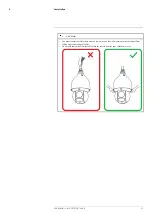
Page 17: ... the safety chain between the camera and the wall mount to protect the camera from falling while connecting the cables Do not hold the camera from the cable Hold the camera from the edge of the dome cover LX400116 r 1 0 57307 57307 en US 11 ...

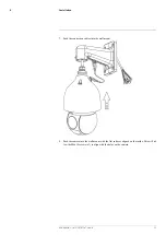
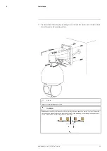
Page 18: ...nnection cables into the wall mount 8 Push the camera into the wall mount with the flat surfaces aligned on the inside This will al low the M6x14 screws x3 to align with the holes on the camera LX400116 r 1 0 57307 57307 en US 12 ...

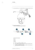
Page 19: ...ernet Connector B O ring C Barrel D Stopper E End Cap 10 1 Fit the o ring around the camera Ethernet connector 10 2 Feed the Ethernet extension cable through the end cap and the barrel then connect the cable to the camera Ethernet connector 10 3 Twist the barrel securely onto the camera Ethernet connector The o ring becomes compressed when the seal is properly tight LX400116 r 1 0 57307 57307 en U...

Page 20: ...ath the teeth at the end of the barrel 10 6 Twist the end cap clockwise to secure it onto the barrel The stopper becomes com pressed and will stick out of the end cap slightly when the seal is properly tight 11 Pull the connection cables through the wall mount and mounting surface 12 Attach the flat washers x4 to the mounting screws x4 LX400116 r 1 0 57307 57307 en US 14 ...

Page 21: ...magery for illustration purposes only WARNING Make sure to install the wall mount bracket in a location that can support the camera s weight If mounting the camera on a drywall surface you must drill at least 2 of the mounting screws through a wooden stud to ensure a stable mount See the diagram below for details LX400116 r 1 0 57307 57307 en US 15 ...

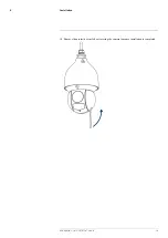
Page 22: ...Installation 4 14 Remove the protective vinyl sheet covering the camera lens once installation is completed LX400116 r 1 0 57307 57307 en US 16 ...

Page 23: ...control the movement of the PTZ camera For instructions on controlling the PTZ camera with the N882 Series NVRs see 6 Controlling the PTZ camera with N882 Series NVR page 18 For instructions on controlling the PTZ camera with the N842 N862 Series NVRs see 7 Con trolling the PTZ camera with N842 N862 Series NVRs page 23 LX400116 r 1 0 57307 57307 en US 17 ...

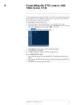
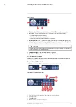
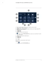
Page 24: ...e view of the PTZ camera and click Main Menu Enter the system user name default admin and password default 000000 if prompted 3 Click SETTING PAN TILT ZOOM 4 Under Channel select the channel your PTZ camera is connected to 5 Under PTZ Type select Remote 6 Click OK You can now control your PTZ camera using the system 6 1 Controlling the PTZ Camera 1 In Live View double click the channel that has th...

Page 25: ... that enters the camera s lens CAUTION Adjust the camera s iris settings to match the environment where the camera is installed Too much light ex posure might result in a very bright camera image 4 Advanced controls Click to open advanced PTZ controls 5 Speed Enter a PTZ speed between 1 slowest and 8 fastest 6 2 Advanced PTZ Controls Advanced PTZ controls can be used to save camera positions and c...

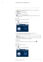
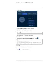
Page 26: ... will save a camera position for quick retrieval To add presets 1 Click to open the PAN TILT ZOOM menu 2 Click the Preset tab 3 Under the Preset text box enter the number of the preset you want to create 4 Move the camera to the desired position and click Set NOTE Click Del Preset to delete a preset 5 Right click to return to the advanced PTZ controls window To go to a preset Under No select the n...

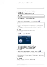
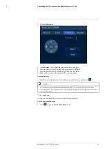
Page 27: ...y two points in a tour 6 2 3 Pattern Patterns automatically cycle the camera between two positions To create a pattern 1 Click to open the PAN TILT ZOOM menu 2 Click the Pattern tab 3 Under Pattern enter the pattern you would like to configure 4 Move the camera into the desired start position and click Start 5 Move the camera into the desired end position and click End 6 Right click to return to t...

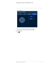
Page 28: ... Click to open the PAN TILT ZOOM menu 2 Click the Border tab 3 Move the camera into the desired left position and click Left 4 Move the camera into the desired right position and click Right To run an auto scan Click LX400116 r 1 0 57307 57307 en US 22 ...

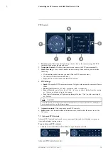
Page 29: ...NVRs please visit lorex com compatibility 7 1 Controlling the PTZ Camera 1 Connect the camera to your NVR as detailed in 3 Connecting the Camera page 4 2 Open the Live View screen for your PTZ camera in single channel view full screen 3 Right click to open the Quick Menu then click Pan Tilt Zoom 4 Enter the system user name and password if prompted The PTZ menu opens 5 Use the on screen controls t...

Page 30: ... and to zoom out Focus Manually control focus level Click to focus on objects further from the camera or to focus on objects closer to the camera Iris Controls the amount of light coming through the lens Click to allow more light or for less CAUTION Adjust the camera s iris settings to match the environment where the camera is installed Too much light ex posure might result in a very bright camera...

Page 31: ...360 4 Tour Click to run the selected tour 5 Not supported 6 Not supported 7 Pattern Click to run the selected pattern 8 Click to open the PAN TILT ZOOM menu where you can set up Presets Tours Pat terns and Auto Scans 9 Auto scan Click to run the selected autoscan 10 Not supported 11 Not supported 7 2 1 Presets Presets will save a camera position for quick retrieval To add presets 1 Click to open t...

Page 32: ...o the desired position and click Setup NOTE Click Del Preset to delete a preset 5 Right click to return to the advanced PTZ controls window To go to a preset Under No select the number of the preset you would like to go to and click 7 2 2 Tours Tours will cycle through a set of presets To create a tour 1 Click to open the PAN TILT ZOOM menu LX400116 r 1 0 57307 57307 en US 26 ...

Page 33: ...eturn to the advanced PTZ controls window To run a tour Under No select the number of the tour you would like to go to and click NOTE There is a 5 second minimum pause between presets Tour panning tilting speed is slower than manual panning tilting speed The reduced speed maximizes reliability We recommend you do not make the camera pan more than 270 between any two points in a tour 7 2 3 Pattern ...

Page 34: ...controls window To run a pattern Under No select the number of the pattern you would like to go to and click NOTE We recommend you do not make the camera pan more than 270 between any two points in a pattern For instructions on how to control the PTZ camera using the smartphone or tablet app refer to your NVR s instructional manual 7 2 4 Auto Scan An auto scan automatically cycles between a left a...

Page 35: ...42 N862 Series NVRs 7 2 Click the Border tab 3 Move the camera into the desired left position and click Left 4 Move the camera into the desired right position and click Right To run an auto scan Click LX400116 r 1 0 57307 57307 en US 29 ...

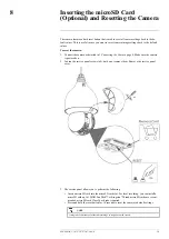
Page 36: ...a is powered on 2 Loosen the service panel screws x4 but do not remove them Remove the service panel cover 3 The service panel allows you to perform the following Insert a microSD card into the microSD card slot For local recording you can install a microSD card up to 128GB SanDisk or Kingston brand microSD cards are recom mended microSD card Class 10 or higher required Press and hold the reset bu...

Page 37: ...ge or camera image is unclear Dome cover is dirty Clean the dome cover with a soft slightly damp cloth Do not use any thing other than water to clean the dome cover as chemicals such as acetone can permanently damage the plastic Image is distorted Digital zoom is activated Activating digital zoom may reduce the resolution of the camera image Zoom out completely to return to the camera s optimal re...

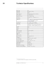
Page 38: ... Manual Speed Max 300 Sec Pan Max 200 Sec Tilt Preset Speed Max 400 Sec Pan Max 300 Sec Tilt Auto Flip 300 Presets 300 Patterns 5 Tours 8 Other PTZ Functions Auto Scans Auto Pan Continuous Rotation Yes Camera OSD Yes HDR Yes Color Night Vision Yes Night Vision Range 150ft 46m 98ft 30m Termination RJ45 Power Requirement PoE 802 3at 12V DC Optional Power Consumption Max 1A 24W Operating Temperature ...

Page 39: ...Technical Specifications 10 10 1 Dimensions LX400116 r 1 0 57307 57307 en US 33 ...

Page 40: ... LX400116 r 1 0 57307 57307 en US 34 ...

Page 41: ......

Page 42: ...her registered trademarks or trademarks of Lorex Corporation and or its subsidiaries All other trademarks trade names or company names referenced herein are used for identification only and are the property of their respective owners Legal disclaimer As our product is subject to continuous improvement Lorex Corporation subsidiaries reserve the right to modify product design specifications prices w...

Reviews: