Connecting the Cameras
Optional
To install your camera:
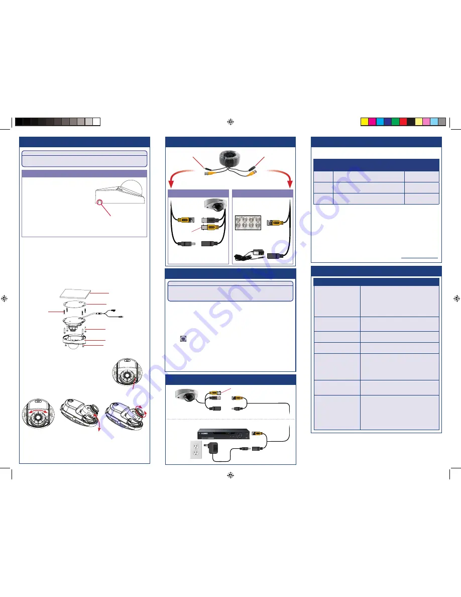
1. To separate the camera cover from the camera base, loosen the
screws located on either side of the camera cover using the
included Allen key.
2. Use the included mounting template to mark holes for the mounting
screws.
3. Drill the holes and then feed the cable through the mounting
surface or cable notch.
NOTE:
Insert the included drywall anchors if installing the camera
in drywall.
Installing the Camera
Extend the cable run for your camera depending on the cable type used.
Additional extension cables sold separately. See table below:
Connect the male power head
and the BNC connector to the
camera.
Connect the BNC connector
to a video input on your DVR.
Connecting the Camera
Cable Notch
LEV2750A_QSG_EN_R3
Problem
Solution
No picture / signal
• Ensure you have used the correct BNC
connector for your DVR. Use the camera’s black
BNC connector when connecting to Lorex HD
DVRs, and the yellow connector for standard
analog DVRs.
• Ensure connections are properly connected.
• Ensure the camera power supply is plugged in.
Picture is too bright
• Ensure your camera isn’t pointed directly at a
source of light (e.g., sun or spot light).
• Move your camera to a different location.
Picture is too dark
• Check the brightness and contrast settings of
the DVR or monitor.
Night vision is not working
• The night vision activates when light levels
drop. The area may have too much light.
Picture is not clear
• Check the camera lens for dirt, dust,
spiderwebs. Clean the lens with a soft, clean
cloth.
• Make sure that the cable run is within the
limitations specified in the section ‘Cable
Extension Options’.
Bright spot in video when
viewing camera at night
• Night vision reflects when pointing a camera
at a window. Move the camera to a different
location.
No audio
• Audio is only supported on Lorex HD DVRs.
Ensure your camera is connected using the
black BNC connector (see ‘Connecting the
Camera’).
• Ensure DVR volume is turned on / turned up.
• Ensure audio function on camera is turned on
(see ‘Disabling Camera Audio’).
• Ensure audio is turned up on viewing device.
Troubleshooting
ATTENTION:
Test your camera prior to selecting a permanent mounting location by
temporarily connecting the camera and cable to your DVR.
Before Installing the Camera
• Decide whether to run the cables through the
wall / ceiling (drilling required) or along
the wall / ceiling.
• If you run the cables along the
wall / ceiling, you must run the
cable through the
cable notch
on
the base. This will keep the camera
base flush to the surface when mounted.
Use pliers to break off the perforated metal
tab on the camera cover, and then align the cable notch in the
camera cover with the cable notch in the camera base.
Connect the female power
head to the included power
adapter.
Camera
DVR
Male Power
Female Power
Setup Diagram
BNC Video
12V DC Power
Camera
Extension Cable
Power Adapter
HD DVR
Cable Extension Options
Option
Cable Type
Max Cable Run
Distance
1
Lorex model MCBL-60BNCU / MCBL-
60BNCU2 BNC Cable (included with camera)
60ft / 18m
2
‘RG59’ or ‘Coax’ or ‘Coaxial BNC’ Siamese
(Video and Power)
300ft / 92m
3
‘RG59’ or ‘Coax’ or ‘Coaxial BNC’ (Video
Only)
2
800ft / 242m
Notes:
1. The extension cable must be a single stretch of cable between the
DVR and camera. You cannot connect multiple extension cables to
each other.
2. For cable runs above 300ft / 92m (option 3), you must connect the
power adapter directly to the camera, rather than at the end of the
extension cable.
3. Indicators that your cable run may be too long:
• Video is permanently black & white (even during day time)
• Video is unclear, soft, or distorted
4. For more information on extension cables, visit
lorextechnology.com
Adjustment screw
A) Turn the lens
holder up to 45°
B) Tilt the lens
module up to 90°
C) Rotate the lens
module 360°
4. Connect cables as shown in the section “Connecting the Camera”.
5. Mount the camera base to the surface using the
provided mounting screws. Make sure
all screws are fastened tightly.
6. Use a Philips head screwdriver (not included)
to loosen the lens module adjustment screw.
Do not loosen all the way.
7. Adjust the angle of the camera
as needed:
01
01
01
Mounting Surface
Mounting Template
Drywall Anchors
Mounting Screws
Camera Cover
Camera Mount Screw
8. Tighten the adjustment screw when finished.
9. Cover the camera base with the camera cover.
10. Tighten the screws on either side of the camera cover.
Connecting the Cameras
Disabling Camera Audio
ATTENTION:
Audio recording without consent is illegal in certain jurisdictions. Lorex
Corporation assumes no liability for use of its products that does not
conform with local laws.
Audio is enabled by default. To disable camera audio through a Lorex HD DVR:
1. In Live View, double-click the camera channel to open in full-screen.
2. Right-click and then click
PAN/TILT/ZOOM
. Enter the system user name and
password if prompted. The PTZ menu opens.
NOTE:
If prompted, set the control mode and protocol for the channel that the
camera is connected to in the
PAN/TILT/ZOOM
setting page.
3. Click the arrow in the PTZ control window to show advanced controls.
4. Click
. In Menu Operation, click
Enter
. The OSD menu appears over the camera
image.
5. Select the
Advanced
menu using the on-screen controls.
6. Select the
Audio Mode
option and choose
OFF
.
7. Click
Enter
.
NOTE:
These instructions are based on current Lorex HD DVR interface. If you are
not able to access your DVR’s OSD menu by following these steps, please use the
instructions in your DVR manual instead.
For optional connection to
standard analog DVRs


