background image


Important Safeguards 


3

ENG 

Important Safeguards 

In addition to the careful attention devoted to quality standards in the manufacture process of your video 
product, safety is a major factor in the design of every instrument. However, safety is your responsibility 
too. This sheet lists important information that will help to assure your enjoyment and proper use of the 
video product and accessory equipment. Please read them carefully before operating and using your 
video product. 


1.


Read and Follow Instructions

 - All the 

safety and operating instructions should be 
read before the video product is operated. 
Follow all operating instructions. 


2.


Retain Instructions

 - The safety and 

operating instructions should be retained for 
future reference. 


3.


Heed Warnings

 - Comply with all warnings 

on the video product and in the operating 
instructions. 


4.


Polarization

 - Do not defeat the safety 

purpose of the polarized or grounding-type 
plug. 


5.


Power Sources

 - This video product should 

be operated only from the type of power 
source indicated on the marking label. If you 
are not sure of the type of power supply to 
your location, consult your video dealer or 
local power company. For video products 
intended to operate from battery power, or 
other sources, refer to the operating 
instructions. 


6.


Overloading

 - Do not overload wall outlets of 

extension cords as this can result in the risk 
of fire or electric shock. Overloaded AC 
outlets, extension cords, frayed power cords, 
damaged or cracked wire insulation, and 
broken plugs are dangerous. They may result 
in a shock or fire hazard. Periodically examine 
the cord, and if its appearance indicates 
damage or deteriorated insulation, have it 
replaced by your service technician. 


7.


Power-Cord Protection

 - Power supply 

cords should be routed so that they are not 
likely to be walked on or pinched by items 
placed upon or against them, paying 
particular attention to cords at plugs, 
convenience receptacles, and the point where 
they exit from the video product. 

8.


Ventilation

 - Slots and openings in the case 

are provided for ventilation to ensure reliable 
operation of the video product and to protect 
it from overheating. These openings must not 
be blocked or covered. The openings should 
never be blocked by placing the video 
equipment on a bed, sofa, rug, or other 
similar surface. This video product should 
never be placed near or over a radiator or 
heat register. This video product should not 
be placed in a built-in installation such as a 
bookcase or rack unless proper ventilation is 
provided or the video product manufacturer’s 
instructions have been followed. 


9.


Attachments

 - Do not use attachments 

unless recommended by the video product 
manufacturer as they may cause a hazard. 


10.


Water and Moisture

 - Do not use this video 

product near water. For example, near a bath 
tub, wash bowl, kitchen sink or laundry tub, in 
a wet basement, near a swimming pool and 
the like.  


Caution: Maintain electrical safety. Power line 
operated equipment or accessories 
connected to this unit should bear the UL 
listing mark of CSA certification mark on the 
accessory itself and should not be modified 
so as to defeat the safety features. This will 
help avoid any potential hazard from electrical 
shock or fire. If in doubt, contact qualified 
service personnel. 


11.


Accessories

 - Do not place this video 

equipment on an unstable cart, stand, tripod, 
or table.  
The video equipment may fall, 
causing serious damage to the 
video product. Use this video 
product only with a cart, stand, 
tripod, bracket, or table 
recommended by the 
manufacturer or sold with the 
video product.  
Any mounting of the product should follow 
the manufacturer’s instructions and use a 
mounting accessory recommended by the 
manufacturer. 
 

Installation 

o


A polarized plug has two blades with 
one wider than the other. 

o


A grounding type plug has two 
blades and a third grounding prong. 

o


The wide blade or the third prong is 
provided for your safety. 

o


If the provided plug does not fit into 
your outlet, consult an electrician for 
replacement of the obsolete outlet 

Summary of Contents for LW2101 series

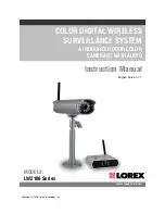
Page 1: ...Copyright 2008 Lorex Technology Inc COLOR DIGITAL WIRELESS SURVEILLANCE SYSTEM INDOOR OUTDOOR COLOR CAMERA S WITH AUDIO Instruction Manual English Version 1 1 www lorexcctv com MODELS LW2100 Series ...

Page 2: ...ay be of sufficient magnitude to constitute a risk of electric shock The exclamation point within an equilateral triangle is intended to alert the user to the presence of important operating and maintenance servicing instructions in the literature accompanying the appliance WARNING TO PREVENT FIRE OR SHOCK HAZARD DO NOT EXPOSE THIS UNIT TO RAIN OR MOISTURE CAUTION TO PREVENT ELECTRIC SHOCK MATCH W...

Page 3: ...enience receptacles and the point where they exit from the video product 8 Ventilation Slots and openings in the case are provided for ventilation to ensure reliable operation of the video product and to protect it from overheating These openings must not be blocked or covered The openings should never be blocked by placing the video equipment on a bed sofa rug or other similar surface This video ...

Page 4: ...rds 16 Safety Check Upon completion of any service or repairs to this video product ask the service technician to perform safety checks recommended by the manufacturer to determine that the video product is in safe operating condition 17 Wall or Ceiling Mounting The cameras provided with this system should be mounted to a wall or ceiling only as instructed in this guide using the provided mounting...

Page 5: ...wever there is no guarantee that interference will not occur in a particular installation If this equipment does cause harmful interference to radio or television reception which can be determined by turning the equipment on and off the user is encouraged to try to correct the interference by one or more of the following measures o Reorient or relocate the receiving antenna o Increase the separati...

Page 6: ...9 Camera Installation 9 Connecting Camera Power 10 Wireless Connection LED Indicator 11 Viewing Mode 12 Advanced Menu Mode 13 Camera Pairing 14 Troubleshooting 15 Appendix 1 Receiver Specifications 16 Appendix 2 Camera Specifications 16 Appendix 3 Digital Wireless Technology 18 The Digital Wireless signal transmission type used by the Lorex LW2100 series is also known as FHSS Frequency Hopping Spr...

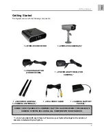
Page 7: ...E 1 x RECEIVER ANTENNA 1 x CAMERA ANTENNA S 1 x WIRELESS CAMERA S 1 x POWER ADAPTOR S FOR CAMERA 1 of each provided with each Camera Please see your System Package for the number of cameras included with your System 1 x CAMERA BATTERY PACK S CHECK YOUR PACKAGE TO CONFIRM THAT YOU HAVE RECEIVED THE COMPLETE CAMERA SYSTEM INCLUDING ALL COMPONENTS SHOWN ABOVE ...

Page 8: ...and Video ends of the cable to a TV VCR or other viewing device 7 DC 9V INPUT Connection port for the 9V Power Adaptor provided with this system Connect the Power Adaptor to a power source NOTE It is recommended that the receiver be connected to a power surge bar to protect the equipment from damage Wireless Receiver Buttons 1 Buttons Press the Up Down Left or Right buttons to navigate in Menu Mod...

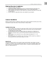
Page 9: ...location for the camera that provides a clear view of the area you want to monitor which is free from dust and is not in line of sight to a strong light source or direct sunlight Avoid installing the cameras where there are thick walls obstructions or interference i e transformers microwave ovens or other electrical equipment between the Cameras and the Receiver Select a location for the camera th...

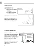
Page 10: ...ra can be powered either by using the provided Power Adaptor or using the included Battery Pack with 4 x AA Batteries NOTE Wireless cameras require a power source either an electrical outlet or battery power to operate If you plan to permanently mount the camera in a location it is recommended to use the included Camera Power adaptor to prevent interruptions in the image as the battery adaptor is ...

Page 11: ...o the Camera To turn the Camera ON of OFF simply connect the BatteryPack NOTE It is recommended to remove the battery pack from the camera when not in use Wireless Connection LED Indicator When the Receiver and Camera are connected The Camera will have IR LEDs indicating that there is a connection The Wireless receiver Wiresless Indicator LED will be lit Battery Connect the Camera Battery Adaptor ...

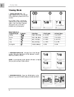
Page 12: ...ta Rate VGA Frames QVGA Frames Perfect 1062 1280 Kbps 5 10 FPS 15 30 FPS Good 725 1062 Kbps 3 5 FPS 12 20 FPS Fair 543 725 Kbps 2 4 FPS 8 15 FPS Low 250 543 Kbps 0 1 FPS 0 4 FPS No Signal Under 250Kbps 0 FPS 0 FPS 2 CHANNEL INDICATOR Displays the current channel number Press the CAM Button on the Receiver to switch between available cameras NOTE To automatically switch between channels configure t...

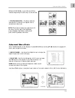
Page 13: ...E Use the Left and Right arrows to change the Audio Volume from 0 off to 20 high 2 SCAN TIME Sets the Auto Sequence to OFF you must press the CAM Button on the receiver to see other channels or 5 Second 10 Second or 15 Second Auto scanning NOTE Before turning on the Auto Sequence make sure all cameras are paired to the System Use the arrows to navigate to each camera Turn each camera to ON or OFF ...

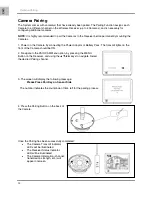
Page 14: ...lights on the front of the Camera should be ON 2 Navigate to the PAIR CAM Menu option by pressing the MENU Button on the Receiver and using the keys to navigate Select the desired Pairing channel 3 The screen will display the following message Please Press Pair Key on Sensor Side The number indicates the countdown of time left for the pairing process 4 Press the Pairing Button on the back of the C...

Page 15: ...a is in range of the Receiver If using the battery adaptor try replacing the Batteries There is Interference with the Camera Picture Make sure that each camera is within range and that there are no large obstructions or interference Try repositioning the camera receiver or both to improve the reception There are problems with the Audio Ensure that the volume on the TV is ON Make sure that the soun...

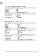
Page 16: ...TX Power 13 5dBm Data Rate 2Mbps Modulation GFSK TX Range 328 ft 100m Line in Sight Image Sensor Type 1 4 VGA CMOS Image Sensor Effective Pixel H 640 V 480 Image Processing Motion JPEG Image Resolution H 640 V 480 5 7fps H 320 V 240 20fps Lens 3 6mm F 2 0 Viewing Angle H 54 V 37 AGC On AES ERS Electric Rolling Shutter Power Requirement 5 0Vdc 10 Power Consumption 450mA Max with IR LED 345mA Max wi...

Page 17: ... the analog transmission signal allowed by authorities around the Globe see next 2 slides for a comparison When an image is captured by the camera it is instantly converted from an analog to digital signal and packaged into small packets With each successful transmission via the 2Mhz paths discussed above the packets of information containing images are delivered to the receiver and decoded into a...

Reviews: