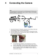
Connecting the Camera
4
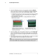
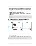
4. Connect the RS485 connectors on the extension cable to the
RS485
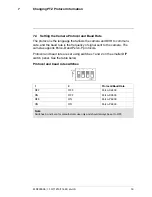
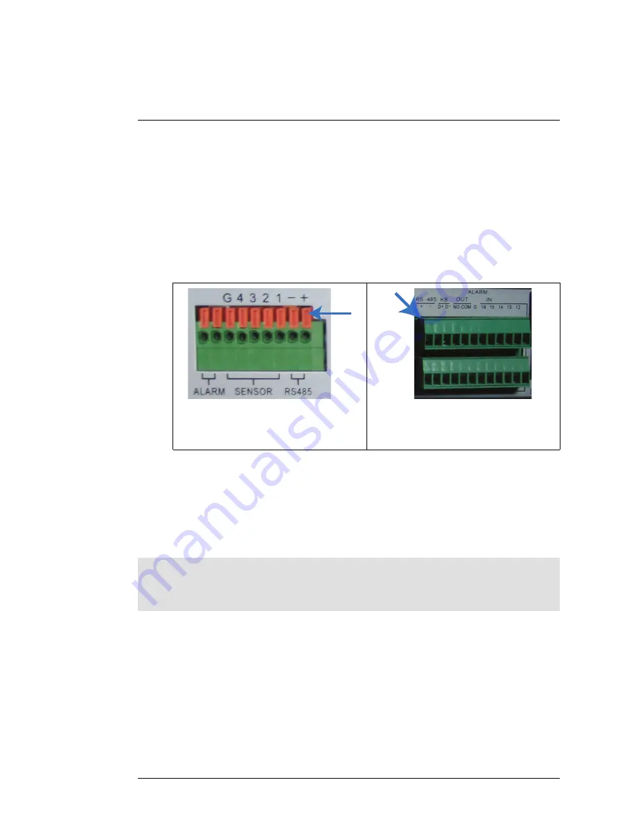
block on your DVR. The layout of the RS485 block may differ depending
on your DVR model (common terms include RS485, RS422, or PTZ).
• The RS485 connectors are a pair of bare wires. The red wire is positive
(
+
) and is connected to the
+
port, and the black wire is negative (
-
)
and is connected to the
-
port.
• Most DVRs either use screws or a spring loaded lock to hold the
RS485 wires in place.
Spring loaded alarm block
: Insert a
screwdriver into the lock above the port,
and then insert the wires.
Screw lock alarm block
: Tighten
screws above ports to secure wires.
5. Connect the BNC cable on the extension cable to one of the
Video Input
ports on the DVR. Make note of the port number where you connect the
camera, as it will be used when configuring the DVR to communicate with
the camera.
6. Connect the power connector on the 100ft extension cable to the included
power adapter. Plug the power adapter into a power outlet.
Note
Because this is a high-powered PTZ camera, the power cable cannot be extended beyond
100ft. To extend the BNC video or RS485 cables, see 5.2
Extension Cables
, page 6.
#LX400006; r. 1.0/11219/11445; en-US
5
Summary of Contents for LZC7092B
Page 1: ...Instruction Manual LZC7092B 10X PTZ Camera ...
Page 2: ......
Page 3: ...Instruction Manual LZC7092B 10X PTZ Camera LX400006 r 1 0 11219 11445 en US iii ...
Page 6: ......
Page 29: ......
Page 31: ...Manuel d utilisation Caméra LZC7092B 10X PTZ ...
Page 32: ......
Page 33: ...Manuel d utilisation Caméra LZC7092B 10X PTZ LX400006 r 1 0 11447 11448 fr CA iii ...
Page 36: ......
Page 38: ......
Page 67: ......
Page 69: ...Manual de instrucciones Cámara PTZ 10X LZC7092B ...
Page 70: ......
Page 71: ...Manual de instrucciones Cámara PTZ 10X LZC7092B LX400006 r 1 0 11446 11448 es MX iii ...
Page 74: ......
Page 76: ......
Page 104: ......
Page 105: ......

