background image


- 54 - 

Limited Warranty 


Warranty:

  Subject to the exclusions and limitations below, LOREX warrants to the initial end-user purchaser that the 

product will be free from defects in material and workmanship for a period of one year from the date of purchase. For valid 
warranty claims made during the warranty period, upon proof of purchase, defective products will, at the election of 
LOREX, be repaired or replaced without charge. Any products repaired or replaced within the warranty period, shall be 
warranted by LOREX to the initial end-user purchaser for 90 days from the return shipment date, or the remainder of the 
warranty term, whichever is longer, and if outside of the warranty period then for 90 days from the return shipment date. 
Products and parts may be replaced with refurbished items, and the products and parts replaced become the property of 
LOREX. You are responsible for all shipping costs associated with the return of the defective products for warranty 
service. 
 

Exclusions and Limitations:

 Any of the following will void this warranty:  

1. 

installation or use of the product other than strictly in accordance with the instructions contained in the product’s 
instruction manual;  

2. 

if the product is subjected to operating conditions (including atmospheric, moisture and humidity conditions) 
outside of the acceptable conditions specified in the product's instruction manual;  

3. 

if the product is subjected to misuse or abuse;  

4. 

if the product is subjected to electrical short circuits or transients, accident, fire, flood or Acts of God;  

5. 

adjustment, maintenance or repair of the product other than in accordance with LOREX approved procedures; 
and use of replacement parts other than those specified by LOREX. 


LOREX MAKES NO CLAIMS OR WARRANTIES OF ANY KIND WHATSOEVER REGARDING THE PRODUCT’S 
ABILITY OR EFFECTIVENESS IN PREVENTING OR REDUCING THE RISK OF, OR DAMAGES RESULTING FROM, 
LOSS OR THEFT OF PROPERTY OR PERSONAL INJURY. 
 
THIS LIMITED WARRANTY IS IN LIEU OF ALL OTHER WARRANTIES, EXPRESS OR IMPLIED, INCLUDING, BUT 
NOT LIMITED TO, ANY IMPLIED WARRANTY OF MERCHANTABILITY OR FITNESS FOR A PARTICULAR USE OR 
PURPOSE. 
 

REPAIR


OR


REPLACEMENT


AS


PROVIDED


UNDER


THIS


LIMITED


WARRANTY


IS


THE


EXCLUSIVE


REMEDY


OF


THE


PURCHASER.


LOREX


SHALL


IN


NO


EVENT


BE


LIABLE


FOR


ANY


SPECIAL,


INDIRECT,


INCIDENTAL,


PUNITIVE,


OR


CONSEQUENTIAL


DAMAGES


OF


ANY


KIND


OR


CHARACTER,


INCLUDING,


WITHOUT


LIMITATION,


PERSONAL


INJURY,


LOSS


OF


REVENUE


OR


PROFITS,


FAILURE


TO


REALIZE


SAVINGS


OR


OTHER


BENEFITS,


OR


CLAIMS


AGAINST


THE


PURCHASER


BY


ANY


THIRD


PERSON,


EVEN


IF


LOREX


HAS


BEEN


ADVISED


OF


THE


POSSIBILITY


OF


SUCH


DAMAGES. 


No claims or statements regarding the product, whether written or verbal, by salespeople, retailers, dealers or distributors, 
that are not contained in this limited warranty or in the owner's manual are authorized by LOREX and do not modify or 
expand this warranty. 
 
Some countries, states, or provinces do not allow the exclusion or limitation of implied warranties or the limitation of 
incidental or consequential damages for certain products supplied to consumers or the limitation of liability for personal 
injury. To the extent that such restrictions on limitations apply to the products, the above limitations and exclusions may 
be limited in their application. In that case, when the implied warranties are not allowed to be excluded in their entirety, 
they will be limited to the duration of the applicable written warranty, and if damages may not be limited then the above 
limitations on damages apply, but only to the greatest extent permitted by local law. 
 

Warranty and Non-Warranty Service:

 Contact the dealer that sold you this product, during the warranty period if 

applicable, to obtain service. Non-warranty service is subject to LOREX's then current service terms and prices. If the 
dealer fails to respond, cannot be reached or fails to provide you with the required service, you may obtain service directly 
from LOREX by calling our service department at (866) 344-4674. You must provide LOREX with the defective product's 
model number, serial number, date of purchase, sales or invoice number, proof that you were the original end-user 
purchaser for warranty work, and a brief description of the problem. You must obtain a return authorization number from 
the service department and must mark the number clearly on the shipping box. You must ship the item prepaid in 
appropriate packaging to the following address:  
 

Strategic Vista Corp. 

Attention: Repair Department, 

300 Alden Rd, 

Markham, Ontario, Canada, 

L3R 4C1 


Summary of Contents for QLR440

Page 1: ...1 Digital Video Capture Card QLR440 Installation User Manual Strategic Vista Corp...

Page 2: ...environment This equipment generates uses and can radiate radio frequency energy and if not installed and used in accordance with the instruction manual may cause harmful interference to radio communi...

Page 3: ...cket or table recommended by the manufacturer or sold with the product Any mounting of the product should follow the manufacturer s instructions and should use a mounting accessory recommended by the...

Page 4: ...1 Entering the Setup Mode 20 2 Main System Options 20 3 Camera Setup 24 4 Schedule Recording Options 25 5 Motion Detect Setup 26 6 Sensor Input Output Options 27 7 Speaker and Relay Setup 28 9 Mail S...

Page 5: ...ions Motion Detect Activation Recording may be set to occur upon observed motion on a selected camera which maximizes the amount of video storage on the hard drive Also further configuration allows se...

Page 6: ...following components are present QLR440 4 Port PCI Board I O Alarm Board QLR440 software installation CD Installation and User Manual Power Supply Cable Minimum System Requirements Processor Pentium...

Page 7: ...wer Supply Connects to the supplied power cable allowing for cameras to receive power directly from the computer s Main Board GPIO Port Connects to the Alarm Block module if being used NOTE 1 In order...

Page 8: ...matically if it did not receive any response from the system for more than 5 minutes WARNING TURN OFF YOUR PC AND UNPLUG IT BEFORE OPENING THE COMPUTER AND INSERTING THE HARDWARE Installation Procedur...

Page 9: ...PC Reset Control of the VISTAPRO 4 and I O Alarm block Device for Auto Rebooting Watchdog function Below is the complete picture of the VISTAPRO 4 and connected I O Alarm Block PC Reset Pin Cable Soc...

Page 10: ...other side of PC Power Pin connection cable red cable from the I O Alarm board to the Power Pin on the PC main board Device for remote PC Power On function QDR TELS accessory module 7 Connect the othe...

Page 11: ...er side of PC Reset Pin connection cable yellow cable with the Reset Switch connection cable on the front of PC case Required for Watchdog function 10 Close the PC case cover VISTAPRO PC Reset Pin Cab...

Page 12: ...cessfully installed the VISTAPRO Hardware Note that the DVR may be expanded by adding a second QLR440card to the PC If adding a second card use the same procedure as above excluding steps 6 9 Camera1...

Page 13: ...he DVR cards to the PCI slot Windows will automatically detect the existing card and the following message dialog appears automatically The first time you install the video card Insert the DVR Softwar...

Page 14: ...l be shown Click the Continue Anyway button to proceed 5 After the video driver installation finished click the Finish button Audio Driver 6 You need to continue installing the audio driver Select Ins...

Page 15: ...re CD Select the driver for your DVR card from the list Click also Next button here 8 When the driver is located the below screen will be shown Click the Continue Anyway button to proceed 9 After the...

Page 16: ...irectory on the provided CD Follow the on screen directions to complete the installation of the software You may be prompted to install DirectX version 8 1 if your current version is lower If prompted...

Page 17: ...erface screen will open as shown below There are several view modes for efficient monitoring such as single screen division screen and auto switching modes Pan Tilt Zoom Controls are available from th...

Page 18: ...The most recent events are shown here A complete detailed event list may be viewed by double clicking in this area Any event related to a change to system setup recording connections and startup shutd...

Page 19: ...rol Move the slider to control the audio volume Record Control The first button in this group enables disables any recording schedules defined in the Setup mode Note that this affects all schedules in...

Page 20: ...e Setup button from the main application window to enter the setup mode You will be asked to enter your Username and Password before proceeding to Setup mode The defaults for these are Username admin...

Page 21: ...nputs are associated to video channels in numerical order ex Audio1 Channel1 The Audio icon will be displayed on the screen of the selected channel In search mode a white line on the timetable indicat...

Page 22: ...ithout any insertion in all space Backup Selected recordings may be backed up to another drive or folder Default Backup Directory C DVRBACKUP Manual backup You can backup a recorded file of specific d...

Page 23: ...IP address range you can appoint specific IP addresses to accept Denied IP address Input the IP address that will be denied Accepted IP address in denied Input the IP address that you wish to be exem...

Page 24: ...video quality Setup the record video image quality of the selected camera Record maximum possible frames Setup the record maximum frame rate of the selected camera 1 30 fps Record all frames when even...

Page 25: ...tion occurs in the appointed motion detection region Sensor Record when the associated external sensor input is activated Event M or S Record when an alarm event motion detection or sensor input occur...

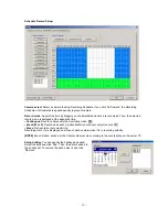
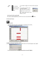
Page 26: ...ase Clear specific regions of the grid by mouse dragging on the viewer as desired Test start Start the test of the motion detection on the viewer Test stop Stop the test The Motion Detect symbol is di...

Page 27: ...r when this input is triggered 1 60 sec Camera recording association Select cameras to be associated and recorded together when this sensor input is activated Output association Select the output cond...

Page 28: ...rm occurs 1 60 sec Delay time Set a desired delay time The speaker will sound after this delay time expires 1 10 sec Relay out 1 8 Relay out Enable If checked the relay output is enabled Description A...

Page 29: ...rame during while the e mail function will be able to activate Minimum interval between two consecutive mails Sets the minimum interval between two consecutive e mails 1 60 min Delay for capturing ima...

Page 30: ...stered ID password is used when accessing the system remotely from the Client or Search program A user must be set up in the area in order to gain remote access Clicking ADD or MODIFY brings up the wi...

Page 31: ...hutdown Remote Search Download Connection Remote Setup User NO NO NO YES YES YES NO Power User NO NO YES YES YES YES NO Administrator YES YES YES YES YES YES YES Administrator password Changes the adm...

Page 32: ...he recorded data on the DVR Server system via Network Internet Starting the Search program Open the search program by double clicking the Search icon on the desktop or clicking the Search button from...

Page 33: ...ows dates that have recorded data Blue date Has recorded data Green date Currently selected date To search other month use and Months with no recorded data will be skipped Click the date you want to s...

Page 34: ...only Motion Detection Recording data Red S Display only Sensor Recording data Orange 4 Playback the selected data recorded Use the following controls to adjust playback specs and direction Play tool...

Page 35: ...nverted to an AVI file which will be able to be played back on any PC After clicking the Store to AVI button select the compression type and click Start Then the conversion to AVI file will be progres...

Page 36: ...region become expand narrow as Zoom In Out Also you can move the region red rectangular by dragging using mouse Image Processing User can process the current capture image using various image process...

Page 37: ...ternet or Dial up 1 Introduction to the Client Window Open the DVR Client program by double clicking the DVR Client icon on the desktop The functions controls within this window are nearly identical t...

Page 38: ...the server name and connection speed Log View The most recent connection status events are shown here Connect Button Click here to connect disconnect with the remote server Call Button Click this but...

Page 39: ...ork speed status is shown on the main window The Connection button will be changed to a blue color while connected Clicking this button will disconnect the client from the server and button color will...

Page 40: ...anel input the client setup login password set in server registration setup panel of Client Setup mode and click OK NOTE The default password for local setup login of the Client is 1111 You can change...

Page 41: ...DD to overwrite when full On When the selected record drive is full the DVR will begin overwriting the drive from the beginning Off When the selected record drive is full the DVR will stop recording R...

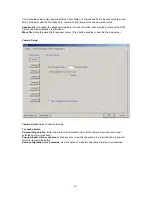
Page 42: ...s minimized Wave file Setup the wave file for speaker output Play button enables to hear the file in advance Camera Setup Camera Select Select a camera to setup For each camera Prerecording duration E...

Page 43: ...ime Continuous Record continuously the monitoring video Event M or S Record when event motion detection or sensor output occurs Erase Not record but only monitoring Recording mark R is displayed on sc...

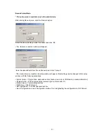
Page 44: ...gging into the DVR This user name must be enabled in the Server setup NOTE 1 If the server is using a Static IP address enter the Static IP address to connect in the IP Product No section 2 If the DVR...

Page 45: ...he connection is successful the setup window will appear Most settings can be changed in this setup window with the following exceptions System Setup Record drive advanced section backup auto check US...

Page 46: ...lt 2000 When the Search tries to connect to the DVR Server you have only to input the video port number 2000 User ID User ID registered in server to search remotely Password Password registered in ser...

Page 47: ...back by 1 channel mode Quad View User can see the screen by 4 channel quad mode by clicking Quad button By double clicking on the screen 1 channel display mode and quad mode are changed alternately Ti...

Page 48: ...layed on screen How to play the Audio recording data After selects only one channel being audio data recorded you make play with play button 6 Advanced Functions Download In the Remote Search use when...

Page 49: ...ction If you click the Local Search button the network connection between DVR Search and Server is disconnected and loads the last recorded data from the local hard disk Then Remote Search button will...

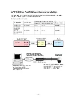
Page 50: ...ART PTZ GC 655N SD 290 DRX 502A CNB CA 1170 all available Rx Rx Tx Tx all available Speed Dome Camera P T Z camera Pin DVR Computer D Rx Tx TD Tx RD RS 485 RS 232C RS 232C to RS 485 Converter pin all...

Page 51: ...a Relay 2 Required Specification of Sensor connecting wire Connection wire that has small internal resistance is recommended Please refer to the following 1 Number of Sensor 8 ea 2 Voltage between se...

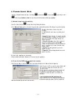
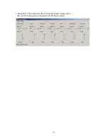
Page 52: ...e Options Properties on Menu bar of the Master volume window shown 3 Check Microphone in case of both Playback and Recording in the Properties window shown Click OK 4 Check Select of Microphone sectio...

Page 53: ...53 5 Check Mute of Microphone section in the Master Volume window shown Then you can do the audio communication with DVR server system...

Page 54: ...IDED UNDER THIS LIMITED WARRANTY IS THE EXCLUSIVE REMEDY OF THE PURCHASER LOREX SHALL IN NO EVENT BE LIABLE FOR ANY SPECIAL INDIRECT INCIDENTAL PUNITIVE OR CONSEQUENTIAL DAMAGES OF ANY KIND OR CHARACT...

Reviews: