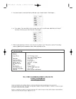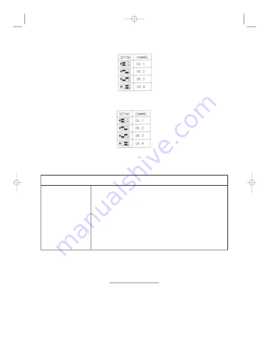
4. Use a small screw driver to adjust the dip switch pins to your desired channel. (See diagram.)
SPECIFICATIONS
Camera
Image Device
1/3” CCD Image sensor
512 H x 492 V picture elements
Resolution
Horizontal 420 T lines
Scanning System
2:1 Interlace
Minimum Illumination
0.5 Lux @ F 1.4
Shutter Control
Auto 1/60 – 1/100,000
Electronic Shutter
Built-In
Lens
3.6mm
Video Output
1.0-vp-p 75 Ohm
Power Requirement
12V DC Adapter (included)
Operating Temperature
14°F – 140°F
Housings
Black - Aluminum with Bracket
4. (a) For example, if you would like to set the camera to channel 2, move the upper dipswitch pin to the right
position and the lower pin to the left position. (See diagram.)
5. Before replacing the dip switch cover, check the camera picture on your TV/monitor to confirm if it is working
properly. Speak into the microphone to check the sound function as well.
TOLL FREE CUSTOMER SUPPORT 1-888-425-6739
0R VISIT OUR WEBSITE:
www.strategicvista.com
Always use discretion when installing video and/or audio surveillance equipment especially when there is perceived
privacy. Inquire regarding federal, state and/or local regulations applicable to the lawful installation of video and or audio recording or
surveillance. Party consent may be required.
Because our products are subject to continuous improvement, SVC reserves the right to modify product designs and specifications
without notice and without incurring any obligation. E. & O.E.
SG100 Manual - English 6/22/00 10:16 AM Page 4

