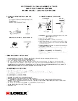
ACCESSORY 2.4 GHz 4 CHANNEL COLOR
WIRELESS CAMERA SYSTEM
MODEL SG6217 - QUICK SET UP GUIDE
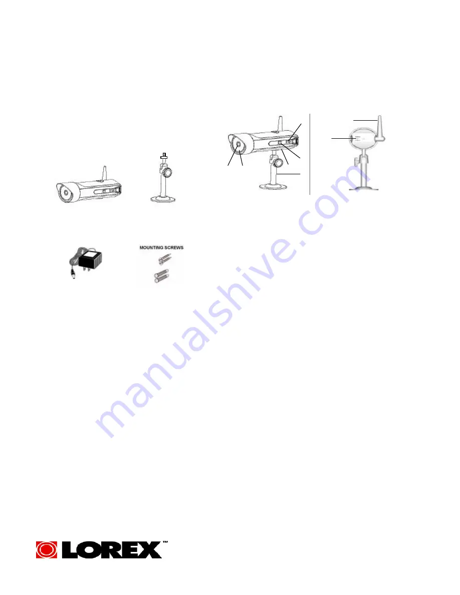
• Wireless Color Camera (with battery compartment)
• Power Adapter
• Metal Mounting Bracket and Screws
1. UNPACK SYSTEM CONTENTS FROM THE
GIFTBOX
2. CAMERA CONTROLS & FUNCTIONS
1. Attach the stand base to the wall or ceiling where you want to install the camera. Locate a wall stud or ceiling
joist and secure bracket using the three supplied screws.
2. Attach the camera to the stand and firmly tighten the swivel..
3. Connect the supplied 9V 500mA DC adapter to the DC IN jack at the rear of the camera and plug it into an electrical outlet.
Your wireless camera has both AC or battery option. When using the AC option with rechargeable batteries, your camera will
automatically switch to back up battery feature during a pow er outage providing you with uninterrupted power to the camera. The
battery option also provides you the flexibility to move the camera from room to room.
WIRELESS CAMERA - AC OPTION ONLY
1. Ensure the power switch on the camera is turned OFF.
2. Connect one end of the power supply to the DC IN jack located at the back of the camera. Plug the
other end into an electrical outlet
WIRELESS CAMERA - USING BATTERIES
1. Ensure the power switch on the camera is turned OFF.
2. Carefully slide open the battery compartment (bottom of camera)
3. Insert 4 alkaline ‘AA’ batteries (not included) into the camera battery compartment. Close compartment. WARNING: TO
PREVENT INJURY AND/OR DAMAGE TO THE UNIT, ENSURE THE BATTERIES ARE ALIGNED PROPERLY AND BATTERY
TYPES ARE NOT MIXED..
4. Connect one end of the power supply to the DC IN Jack located at the back of the
camera. Plug the other end into an electrical outlet.
5. Turn camera “ON”
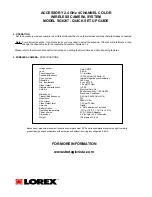
3. WIRELESS CAMERA – INSTALLATION
FRONT/ SIDE VIEW
REAR VIEW
POWER ADAPTER
WIRELESS COLOR CAMERA
2
6
4
3
1
5
7
8
1. Microphone
– Built-in condenser microphone provides listen-in audio
capability from camera to TV
2. Lens
– Color CMOS Image Sensor
3. Channel Selector Switch
– Slide switch for channels 1-4
4. ON/OFF Power Switch
– Controls power to the camera. Note: Please
ensure that you set the switch to the OFF position before plugging the
AC adapter into the unit
5
.
Battery Compartment
– Optional 4 “AA” batteries (not included) can
be used to power the camera
6. Bracket
– Metal bracket connects to camera for mounting to walls,
ceilings or table
7. DC IN Jack
– Connects to the 9V DC (500mA) adapter.
8. 2.4GHz Antenna
– High gain dipole antenna sends audio and video
signals to the receiver
MOUNTING BRACKET


