background image

iv


Setting Camera Codes and Protocols

Prior to installation, setup ID address and communication protocol of your camera. Make sure the 
camera is powered 

OFF

 when resetting IDs or protocols after installation. When you have set the 

new IDs or protocols, power on the camera to implement the changes.

Camera Self-Test

Prior to mounting the camera, power on the camera to activate a self-test. To activate the 
camera’s self-test, power-on the camera—the camera will automatically tilt up/down scanning and 
then pan hoizontal scanning for approximately 20~30 seconds. The camera will stop at Preset 
Point 1. The Mini Speed Dome Camera is now in normal mode.

Summary of Contents for SG7382

Page 1: ...INSTRUCTION MANUAL English Version 1 0 HIGH RESOLUTION MINI PTZ DOME CAMERA WITH 3X OPTICAL ZOOM...

Page 2: ......

Page 3: ...maintenance servicing instructions in the literature accompanying the appliance WARNING TO PREVENT FIRE OR SHOCK HAZARD DO NOT EXPOSE THIS UNIT TO RAIN OR MOISTURE CAUTION TO PREVENT ELECTRIC SHOCK MA...

Page 4: ...munications However there is no guarantee that interference will not occur in a particular installation If this equipment does cause harmful interference to radio or television reception which can be...

Page 5: ...aximum recommended lengths are as follows RG59 U 750ft 230 meters RG61 U 1000ft 305 meters RG11 U 1500ft 457 meters RS485 Cable Please comply with RS485 wiring standards when connecting RS485 cables I...

Page 6: ...et the new IDs or protocols power on the camera to implement the changes Camera Self Test Prior to mounting the camera power on the camera to activate a self test To activate the camera s self test po...

Page 7: ...ng the Camera 5 Cable Pass Through 5 Visible Cable 6 RS 485 Wiring 7 RS 485 Serial Connection 7 RS 485 Aster Connection 8 Connecting the Camera 10 Connectivity Diagram 11 Changing the Camera Address S...

Page 8: ...2...

Page 9: ...et point groups to control moving speed up to 8 phases and retention time for each preset point from 1 99 seconds Preset Point Group Scanning only for Eyeview Protocol up to 16 preset points per group...

Page 10: ...C POWER RS 485 EXTENSION CABLE 1 X MOUNTING BRACKET 1 X INSTRUCTION MANUAL 1 X BNC POWER RS 485CABLE 3 X MOUNTING SCREWS May not be exactly as shown 1 X DC POWER ADAPTOR Optional accessories Included...

Page 11: ...w and prevents tampering To install the camera 1 Drill an opening in your mounting surface large enough for the cables to pass through approximetaly 2 cm 0 79 in in diameter 2 With the pass through ho...

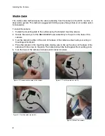
Page 12: ...RS485 Power cable firmly to the port on the base of the camera 3 Tuck the cable into either of the slots in the base of the camera as best suits your wiring or mounting environment 4 Place the camera...

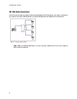
Page 13: ...rmal operation RS 485 Wiring There are two methods for wiring an RS 485 connection Serial and Aster Use either of these recommended wiring methods to prevent malfunction of RS 485 control RS 485 Seria...

Page 14: ...l installation of PTZ cameras In an Aster Connection you need to use a RS 485 distributor to reduce interferance and stabilize the connections Figure 3 1 Aster connection method Note Without a RS 485...

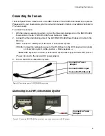
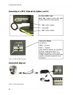
Page 15: ...wer Extension Cable to the following BNC Connect to a BNC port on the DVR or observation system RS485 Connect the terminating wires to the RS 485 port on the DVR keyboard controller or observation sys...

Page 16: ...Black negative Note Additional settings are required on the DVR observation system or keyboard controller to control a PTZ camera Please refer to your observation system s instruction manual for more...

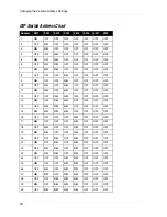
Page 17: ...ras each camera must be set to a unique address using the internal DIP switches See Figure 5 0 Note Make sure the camera is powered off before changing the DIP switches To access the DIP switches 1 Op...

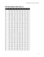
Page 18: ...ON OFF ON OFF OFF OFF OFF 12 OFF OFF ON ON OFF OFF OFF OFF 13 ON OFF ON ON OFF OFF OFF OFF 14 OFF ON ON ON OFF OFF OFF OFF 15 ON ON ON ON OFF OFF OFF OFF 16 OFF OFF OFF OFF ON OFF OFF OFF 17 ON OFF OF...

Page 19: ...OFF 41 ON OFF OFF ON OFF ON OFF OFF 42 OFF ON OFF ON OFF ON OFF OFF 43 ON ON OFF ON OFF ON OFF OFF 44 OFF OFF ON ON OFF ON OFF OFF 45 ON OFF ON ON OFF ON OFF OFF 46 OFF ON ON ON OFF ON OFF OFF 47 ON...

Page 20: ...71 ON ON ON OFF OFF OFF ON OFF 72 OFF OFF OFF ON OFF OFF ON OFF 73 ON OFF OFF ON OFF OFF ON OFF 74 OFF ON OFF ON OFF OFF ON OFF 75 ON ON OFF ON OFF OFF ON OFF 76 OFF OFF ON ON OFF OFF ON OFF 77 ON OF...

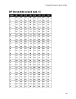
Page 21: ...ON OFF ON OFF OFF ON ON OFF 102 OFF ON ON OFF OFF ON ON OFF 103 ON ON ON OFF OFF ON ON OFF 104 OFF OFF OFF ON OFF ON ON OFF 105 ON OFF OFF ON OFF ON ON OFF 106 OFF ON OFF ON OFF ON ON OFF 107 ON ON OF...

Page 22: ...OFF OFF OFF OFF ON 132 OFF OFF ON OFF OFF OFF OFF ON 133 ON OFF ON OFF OFF OFF OFF ON 134 OFF ON ON OFF OFF OFF OFF ON 135 ON ON ON OFF OFF OFF OFF ON 136 OFF OFF OFF ON OFF OFF OFF ON 137 ON OFF OFF...

Page 23: ...ON OFF OFF OFF OFF ON OFF ON 162 OFF ON OFF OFF OFF ON OFF ON 163 ON ON OFF OFF OFF ON OFF ON 164 OFF OFF ON OFF OFF ON OFF ON 165 ON OFF ON OFF OFF ON OFF ON 166 OFF ON ON OFF OFF ON OFF ON 167 ON ON...

Page 24: ...ON ON ON ON OFF ON 192 OFF OFF OFF OFF OFF OFF ON ON 193 ON OFF OFF OFF OFF OFF ON ON 194 OFF ON OFF OFF OFF OFF ON ON 195 ON ON OFF OFF OFF OFF ON ON 196 OFF OFF ON OFF OFF OFF ON ON 197 ON OFF ON O...

Page 25: ...ON 221 ON OFF ON ON ON OFF ON ON 222 OFF ON ON ON ON OFF ON ON 223 ON ON ON ON ON OFF ON ON 224 OFF OFF OFF OFF OFF ON ON ON 225 ON OFF OFF OFF OFF ON ON ON 226 OFF ON OFF OFF OFF ON ON ON 227 ON ON O...

Page 26: ...ON OFF OFF ON ON ON ON 244 OFF OFF ON OFF ON ON ON ON 245 ON OFF ON OFF ON ON ON ON 246 OFF ON ON OFF ON ON ON ON 247 ON ON ON OFF ON ON ON ON 248 OFF OFF OFF ON ON ON ON ON 249 ON OFF OFF ON ON ON O...

Page 27: ...494K V Video Output 1 0V p p 75 ohms Scanning System 525 lines 2 1 interlace PTZ Protocol Pelco D Pelco P Supported Baud Rate 2400 Pelco D 4800 9600 Pelco P Power Requirement 12 DC 1 0 Amp Operating...

Page 28: ...witched Switch polarity of RS485 wires RS485 faulty wiring connection Check RS485 wiring Camera control is working but not smoothly Mainframe is too far from camera Check wires for error and or set te...

Page 29: ......

Reviews: