background image

v

6. 

Overloading

 - Do not overload wall outlets or extension 

cords as this can result in the risk of fire or electric 
shock. Overloaded AC outlets, extension cords, frayed 
power cords, damaged or cracked wire insulation, and 
broken plugs are dangerous. They may result in a 
shock or fire hazard. Periodically examine the cord, 
and if its appearance indicates damage or deteriorated 
insulation, have it replaced by your service technician.

7. 

Power-Cord Protection

 - Power supply cords should 

be routed so that they are not likely to be walked on or 
pinched by items placed upon or against them. Pay 
particular attention to cords at plugs, convenience 
receptacles, and the point where they exit from the 
product.

8. 

Surge Protectors 

- It is highly recommended that the 

video equipment be connected to a surge protector. 
Doing so will protect the equipment from damage 
caused by power surges. Surge protectors should bear 
the UL listing mark or CSA certification mark.

9. 

Uninterruptible Power Supplies (UPS) 

- Because 

this product is designed for continuous, 24/7 operation, 
it is recommended that you connect the product to an 
uninterruptible power supply. An uninterruptible 
power supply has an internal battery that will keep the 
product running in the event of a power outage. 
Uninterruptible power supplies should bear the UL 
listing mark or CSA certification mark.

Caution:

 Maintain electrical safety. Power line 

operated equipment or accessories connected to this 
product should bear the UL listing mark or CSA 
certification mark on the accessory itself and should 
not be modified so as to defeat the safety features. This 
will help avoid any potential hazard from electrical 
shock or fire. If in doubt, contact qualified service 
personnel.

Important Safeguards

In addition to the careful attention devoted to quality standards in the manufacture process of 
your product, safety is a major factor in the design of every instrument. However, safety is your 
responsibility too. This sheet lists important information that will help to ensure your enjoyment 
and proper use of the product and accessory equipment. Please read them carefully before 
operating and using your product.

General Precautions

1. All warnings and instructions in this manual should be followed.

2. Do not use receivers or video monitors in humid or wet places. 

3. Keep enough space around the product for ventilation. Slots and openings in the storage 

cabinet should not be blocked.

4. It is highly recommended to connect the product to a surge protector to protect from damage 

caused by electrical surges. It is also recommended to connect the product to an 
uninterruptible power supply (UPS), which has an internal battery that will keep the product 
running in the event of a power outage.

5. Remove the plug from the outlet before cleaning. Do not use liquid aerosol detergents. Use a 

water dampened cloth for cleaning.

Installation

1. 

Read and Follow Instructions

 - All the safety and 

operating instructions should be read before the product 
is operated. Follow all operating instructions.

2. 

Retain Instructions

 - The safety and operating 

instructions should be retained for future reference.

3. 

Heed Warnings

  -  Comply  with  all  warnings  on  the 

product and in the operating instructions.

4. 

Polarization

 - Do not defeat the safety purpose of the 

polarized or grounding-type plug.

A polarized plug has two blades with 
one wider than the other.

A grounding type plug has two blades 
and a third grounding prong.

The wide blade or the third prong are 
provided for your safety.

If the provided plug does not fit into your 
outlet, consult an electrician for 
replacement of the obsolete outlet.

5. 

Power Sources

 - This product should be operated only 

from the type of power source indicated on the marking 
label. If you are not sure of the type of power supplied 
to your location, consult your video dealer or local power 
company. For products intended to operate from battery 
power, or other sources, refer to the operating 
instructions.

www.lorextechnology.com

Summary of Contents for Vantage LW2281

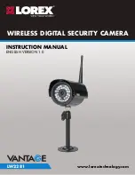
Page 1: ...INSTRUCTION MANUAL ENGLISH VERSION 1 0 www lorextechnology com LW2281 WIRELESS DIGITAL SECURITY CAMERA...

Page 2: ...g flash with arrowhead symbol within an equilateral triangle is intended to alert the user to the presence of uninsulated dangerous voltage within the products enclosure that may be of sufficient magn...

Page 3: ...are for warranty and accessory sales customerservice lorexcorp com Customer Feedback info lorexcorp com Need Help CONTACT US FIRST Online To order accessories visit www lorextechnology com 3 Easy Ways...

Page 4: ...et les ventes d accessoires customerservice lorexcorp com OU 3 maneras sencillas de comunicarse con nosotros Norte Am rica Atenci n al cliente 1 888 425 6739 1 888 42 LOREX Soporte t cnico 1 877 755 6...

Page 5: ...www lorextechnology com support If you require further installation assistance please visit www lorextechnology com installation or contact a professional installer Please refer to the Need Help inser...

Page 6: ...euillez constater qu une fois que les com posantes de ce produit ont t retir es de l emballage vous ne pourrez plus retourner ce produit directement au magasi Favor de leer la gu a de instalaci n r pi...

Page 7: ...design of every instrument However safety is your responsibility too This sheet lists important information that will help to ensure your enjoyment and proper use of the product and accessory equipme...

Page 8: ...pment yourself as opening or removing covers may expose you to dangerous voltage or other hazards Refer all servicing to qualified service personnel 2 Conditions Requiring Service Unplug this product...

Page 9: ...een the radiator and nearby persons Industry Canada Notice This device complies with Industry Canada licence exempt RSS standard s Operation is subject to the following two conditions 1 This device ma...

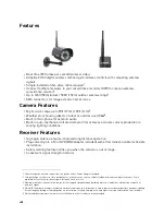
Page 10: ...peration Plugs directly into a TV or DVR BNC adapter included with 4ft termination cable for flexible installation Safety warning feature notifies you when the camera is out of range Convenient signal...

Page 11: ...cations 8 8 Appendix B About Digital Wireless Technology 9 9 Appendix C Facts About Digital Wireless Cameras 10 9 1 Wired vs Wireless Cameras 10 9 2 Does a wireless camera require power 10 9 3 How far...

Page 12: ...x...

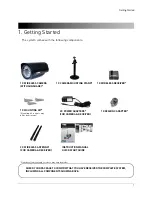
Page 13: ...WIRELESS RECEIVER 2 X POWER ADAPTERS FOR CAMERA RECEIVER Number of cameras and receivers may vary by model 2 X WIRELESS ANTENNA FOR CAMERA RECEIVER 1 X RCA BNC ADAPTER CHECK YOUR PACKAGE TO CONFIRM T...

Page 14: ...ntenna jack at the back of receiver 2 Front LED Glows green to indicate receiver is powered on 3 Pairing Button For details see Pairing Cameras on page 7 2 2 Rear 4 Termination Cable Contains AC Power...

Page 15: ...n For details see Pairing Cameras on page 7 4 Antenna Jack Connect the wireless antenna here 5 AC Power Cable Attention This camera includes an Auto Mechanical IR Cut Filter When the camera changes be...

Page 16: ...ight Avoid installing the camera where there are thick walls or obstructions between the camera and the receiver Avoid installing in a location which requires the wireless signal to pass through cemen...

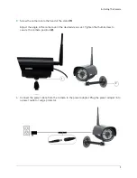
Page 17: ...f the stand 1 Adjust the angle of the camera until the desired view is set Tighten the thumbscrew to secure the camera position 2 1 2 4 Connect the power cable from the camera to the power adapter Plu...

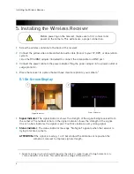
Page 18: ...have clear reception to your camera1 5 1 On Screen Display 1 Signal Indicator The signal indicator shows the strength of the signal being received from the camera The number of bars in the signal indi...

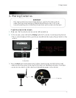
Page 19: ...at the camera and receiver are both powered up 2 On the receiver press and hold the Pairing button for 5 seconds to activate pairing function The on screen displays informs you that you have 30 second...

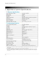
Page 20: ...160 Kb s Modulation GFSK Image Sensor Type 1 4 Color CMOS Image Sensor Effective Pixels H 640 V 480 Image Compression MPEG4 Image Resolution VGA 640x480 Lens 3 6mm F2 0 Field of View Diagonal 63 AGC O...

Page 21: ...ion signal allowed by authorities around the globe When an image is captured by the camera it is instantly converted from an analog to a digital signal and is packaged into small packets With each suc...

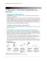
Page 22: ...a typical wireless camera has a range between 250 to 500 feet In a closed environment such as an interior of a house the wireless camera range is between 100 to 165 feet The signal range varies depen...

Page 23: ...secure Yes Lorex digital wireless products feature a wireless transmission method called FHSS Frequency Hopping Spread Spectrum This type of signal is highly resistant to eavesdropping as it generate...

Page 24: ...Try repositioning the camera receiver or both to improve the reception The picture is or has become choppy The picture may become choppy when experiencing a lower frame rate e g 6 frames per second vs...

Page 25: ...there are no obstructions between the camera and receiver Obstructions include walls buildings trees and certain electronic devices Materials containing moisture for example wet leaves may also act as...

Page 26: ...e there is a clear line of sight between the camera and the receiver Clear line of sight Receiver Obstacles There should be little to no obstacles obstructing the line of sight between the camera and...

Page 27: ...that has clear line of sight to the camera During the installation check the reception on your TV DVR or observation system Scenario 2 Multiple Camera Receiver Installation If you are using multiple...

Page 28: ...Copyright 2012 Lorex Technology Inc LW2281 www lorextechnology com Version 1 0...

Reviews: