background image


®


Operating the Plasma Cutter


1.


Adjust the air pressure on your air compressor to 60 – 65 psi for the machine.


2.


Bring the torch tip into direct contact with your work piece edge or, for thicker 
cutting, over a pre-drilled pilot hole. Press the button on the torch to start cutting. 


3.


Ensure that the cutting current is appropriate and adequate for the machine based 
on


the rated thickness of the cutter. 


Note: Below is the consumable assembly on the torch head (Figure 3.1).


Figure 3.1 


Electrode


Torch


Nozzle


Cup


Stand


Guard


14

Summary of Contents for LTP5000D

Page 1: ... LOTOS TECHNOLOGY www uwelding com ...

Page 2: ......

Page 3: ...et Figure 1 1 to protect your eyes from harmful plasma cutting arc radiation Wear safety gloves to protect your hands during operation 2 Connect the machine air inlet on the back of the machine use stand NPT 1 4 industry type D coupler Figure 1 2 to an air compressor Figure 1 3 1 4 and set the air pressure to 65 70 PSI The capacity of air compressor should be larger than 4 0 SCFM 65 PSI Figure 1 1...

Page 4: ...gger of the torch and make sure there is air flow through it 7 Move the torch head to the work piece press the trigger for spacing from the work piece maintain a slight distance approx 1 mm and you will find that the torch will ignite Enjoy cutting 8 Change your consumables tip electrode and cup when they become worn out The correct consumable type for this machine is PCON20 PCON40 PCON90 etc All ...

Page 5: ... LOTOS Plasma Cutters User Manual Version 3 0 July 2017 Copyright Lotos Technology www uwelding com is operated by eBranding Inc 3 ...

Page 6: ...es from Flying Metal or Dirt 7 Pacemakers 7 Cylinder Handing 7 Cralifornia Proposition 65 Warnings 8 Equipment 9 General Overview 9 Main Characteristics 9 Specifications 9 Ideal Cutting Chart 10 Front Panel Diagram 11 Power Cord Plug Connection 12 Installation 13 Instruction Notes 15 Cutting Environment 15 Safety 15 Maintenance and Troubleshooting 15 Plasma Cutter LTP5000D Troubleshooting Flowchat...

Page 7: ...procedures for proper operation of the equipment IMPORTANT Be sure to review the contents of this manual before attempting to operate the equipment This manual should be located where it can be easily referenced by all users of the machine Users This manual assumes that all individuals reading the manual and using the welder cutter are able qualified and or certified to operate this type of machin...

Page 8: ...r working area is nonflammable and explosive free Avoiding Harmful Smoke Gases and Vapors that can injure or kill Welding produces fumes and gases Breathing these fumes and gases can be hazardous to your health Keep your head away from any smoke gases or vapors Avoiding Harmful Arc Emissions Rays that can burn eyes and skin Arc rays from the welding process produce intense visible and invisible ra...

Page 9: ...en under your welding helmet PACEN MAKERS AND WELDING MAGNETIC FIELDS can affect implanted devices Electric arc welding and cutting processes produce intense electric and magnetic electromagnetic fields The function of pacemakers can be affected by strong electromagnetic fields Persons with a pacemaker should not go near welding or cutting operations until they have consulted their doctors and obt...

Page 10: ...tery posts terminals and related accessories contain lead and lead compounds chemicals known to the State of California to cause cancer and birth defects or other reproductive harm Wash hands after handling For Diesel Engines Diesel engine exhaust and some of its constituents are known to the State of California to cause cancer birth defects and other reproductive harm PLEASE READ THIS OPERATION M...

Page 11: ...ting speed Portability Smooth cuts Suitable for stainless steel alloy steel mild steel copper aluminum and other metal materials there are many applications for plasma cutters Specifications Input voltages 120 240 V 1 PH 50 60 Hz Input current 120 V 40 A 240 V 30 A Recommended breaker 50 A 120 V 40 A 240 V Output current 10 50 A Duty cycle 40 C 104 F 60 35 A 120 V 60 50 A 240 V Dimensions with han...

Page 12: ... 35 A 3 10 8 35 A 50 A 35 A 3 8 10 45 A 50 A Not Support 1 2 12 50 A Not Support Aluminum 10 Gauge 3 15 A 50 A 15 A 35 A 1 4 6 25 A 50 A 30 A 35 A 3 10 8 35 A 50 A 35 A 3 8 10 45 A 50 A Not Support 1 2 12 50 A Not Support Production cut thickness are the results of Lotos laboratory testing For optimum cut quality cutting speeds may vary based on different cutting applications All the recommended c...

Page 13: ...er Air Output Switch Plug Ground Connection Figure 2 1 Front Panel Diagram Figure 2 2 Power Cord Plug Connection Figure 2 3 Air Regulator Configuration Pilot Arc Connection 11 Power Cable Air Inlet Rack Air In Compress Meter Cup Power Cable Air Inlet ...

Page 14: ... Figure 2 4 Connecting Cables to Machine Air Compressor Filter Ground Torch Ground Clamp Work Piece 12 ...

Page 15: ...erminal located on the front panel then tighten 3 Ensure that the switch plug of the torch is connected to the switch plug on the panel Check list before Operation 1 Ensure that the cutting machine is properly grounded 2 Ensure that all connectors are connected appropriately and firmly 3 Ensure that power voltages are correct Operating the Plasma Cutter 1 Make sure the machine on off switch is in ...

Page 16: ...r work piece edge or for thicker cutting over a pre drilled pilot hole Press the button on the torch to start cutting 3 Ensure that the cutting current is appropriate and adequate for the machine based on the rated thickness of the cutter Note Below is the consumable assembly on the torch head Figure 3 1 Figure 3 1 Electrode Torch Nozzle Cup Stand Guard 14 ...

Page 17: ...s reduced to allowable range machine can be operated again Maintenance and Troubleshooting 1 Dust created by compressed air should be removed regularly If work environment is polluted with smoke and dust daily maintenance is required 2 Ensure adequate air pressure exists to protect internal components 3 Check all connectors to ensure firm connections 4 Protect machine from water or dampness 5 When...

Page 18: ...oting Flowchat Note If the O C light turns on before operating the machine please call us at 408 739 2329 If the O C light turns on while operating the machine please let the machine take a rest as this is normal operating procedure 16 ...

Page 19: ... 17 ...

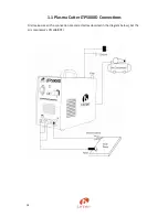
Page 20: ... 1 1 Plasma Cutter LTP5000D Connections First make sure all the connection are corrected as depicted in the diagram below Set the air compressor s PSI at 65 PSI 18 ...

Page 21: ...see if the fan works or not c If problem remains with this step you need to be very careful since the power is on Please wear Insulating gloves and shoes to do this i Pull out the fan socket as highlighted in red ii Plug the power turn on the machine iii Use the voltage meter to test if the voltage between the two pin of the fan socket is around 25 V or not d If the voltage is around 25 V then the...

Page 22: ... Plasma Cutter LTP5000D Other Accessories PT01 GC01 Ground Cable AR01 LCK PCON40 PCON90 CP243 WG10 20 ...

Page 23: ......

Page 24: ...1 ...

Reviews: