Installation, Operation & Maintenance Manual
IM-995
5
Safety & Hazard Warnings
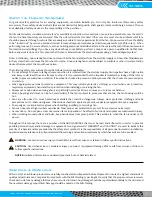
For general safety practices for air moving equipment, see AMCA Bulletin 410. Twin City Fan & Blower offers many safety
accessories. These safety devices include (but are not limited to) belt guards, shaft guards, inlet and discharge screens. The use
and suitability of safety devices is the responsibility of the purchaser.
Facility related safety conditions include fans’ accessibility and location. How easily can non-service personnel access the unit? Is
the fan in a hazardous duty environment? Was the unit ordered for this duty? Other concerns must also be addressed. All fans
should be powered through controls that are easily accessible to service personnel from the fan. Fan power must have the ability
to be “locked out” by service personnel trained in lockout/tagout procedures per OSHA requirements (29CFR1910.147). When
performing lockout, be aware of factors, such as building pressure and additional fans in the system that can influence unwanted
fan rotation (wind milling). If you have any doubt about your ability to perform a task, seek a person qualified to do that task.
Before any work is done on a fan, ensure that the fan is isolated from the electrical supply using a 'lockout/tagout system.'
Note: A stationary, non-rotating fan does not mean that the fan is isolated from the electrical supply or from other fans/dampers
in the system that could cause the fan wheel to rotate. A non-rotating fan could be subject to controls or other circuit protection
devices that may start the fan without notice.
The following safety precautions should be followed, where applicable:
• Do not attempt to slow a rotating wheel even when it is isolated from the electrical supply. Fan impellers have a high inertia
and injury could result from an attempt to stop it. It is recommended that the impeller is isolated by closing off the inlet or
outlet to prevent wind-driven rotation. If an wheel is chocked to prevent rotation, ensure that the chocks are removed prior
to start up.
• Wear appropriate personal protective equipment. This may include protective clothing, eye protection, ear protection,
respiratory equipment, hand and foot protection when installing or servicing the fan.
• Always use caution when entering a fan's air path. High velocity airflow can cause you to lose your balance.
• Motor, bearings and drives can be hot, and similarly if the fan is subject to processes that are hot, the fan housing could be
hot.
• Fans are often used to move hazardous materials that could be dangerous. Always wear protective clothing and take
precautions not to inhale dust/gases. If hazardous chemical vapors are present, respiratory equipment may be required.
• Sharp edges – wear protective gloves when handling, installing or servicing a fan.
• Fans can operate at high decibel sound levels. Wear proper ear protection to protect from excessive noise levels.
• Access doors – Do not open access doors when fan is in operation. The effects of suction and air pressure could result in injury.
• When working around pulleys and belts, keep hands away from pinch points. This pertains to when the fan is under or off
power.
Throughout this manual, there are a number of HAZARD WARNINGS that must be read and adhered to in order to prevent
possible personal injury and/or damage to equipment. Two signal words "WARNING" and "CAUTION" are used to indicate the
severity of a hazard and are preceded by the safety alert symbol. It is the responsibility of all personnel involved in installation,
operation and maintenance to fully understand the warning and caution procedures by which hazards are to be avoided.
WARNING:
Used when serious injury or death MAY result from misuse or failure to follow specific instructions.
CAUTION:
Used when minor or moderate injury or product / equipment damage MAY result from misuse or failure to
follow specific instructions.
NOTICE:
Indicates information considered important, but not hazard-related.
Shipping & Receiving
All Twin City Fan & Blower products are carefully constructed and inspected before shipment to insure the highest standards of
quality and performance. Compare all components with the bill of lading or packing list to verify that the proper unit was received.
Check each unit for any damage that may have occurred in transit. Any damage should be reported immediately to the carrier and
the necessary damage report filed. Damage should be noted on the bill of lading.
Summary of Contents for CD-1261
Page 1: ... 0 1 2121 3 4 1 5 6 ...
Page 2: ... ...
Page 3: ... ...
Page 4: ... ...
Page 5: ... ...
Page 6: ... 0 1 2 3 4 5 6 5 6 7 1 1 5 6 5 6 5 6 1 0 0 ...
Page 7: ... ...
Page 8: ... 0 1 2 0 3 0 ...
Page 9: ... ...
Page 10: ... 0 12 2 0 3 4 5 5 5 0 0 ...
Page 11: ... 6 12 0 0 7 5 5 0 8 0 8 5 0 50 9 4 12 0 0 9 4 0 9 64 0 5 0 0 1 0 0 ...
Page 12: ... 0 2 0 0 3 0 6 6 6 6 6 0 0 0 5 5 0 6 0 ...
Page 14: ... ...
Page 15: ... 0 0 1 1 2 1 1 3 0 4 5 1 0 1 0 0 2 1 2 1 0 0 0 2 1 1 1 1 1 0 0 0 1 0 0 0 1 0 1 6 1 1 ...
Page 17: ... 1 0 3 0 0 1 1 1 71 0 0 1 1 1 0 1 1 ...
Page 18: ... ...
Page 25: ... 8 ...
Page 28: ... 1 7 4 0 4 1 4 1 1 4 1 1 1 4 85 4 4 1 4 1 4 0 6 4 1 1 1 01 0 1 4 6 4 1 1 4 L 1 ...
Page 29: ... 4 ...
Page 30: ... 0 1 2 3 24 3 5 6 4 5 6 4 5 5 1 5 4 74 8 5 9 1 4 27 3 5 4 74 8 5 5 29 13 27 3 1 29 13 5 1 ...
Page 31: ... 8 8 80 1 2 3 5 6 4 5 6 4 5 5 1 5 A 9 1 B 4 27 3 888 7 8 0 B 4 C D 5 29 13 B 27 3 888 7 29 13 ...
Page 32: ... 4 24 3 5 6 4 5 6 4 5 5 4 7 M 7 4 7 N 2 0 7 2 M 0 N M ...
Page 35: ... 8 G 8 0 G 4 88 8E 1 2 3 5 6 4 5 6 4 5 5 1 4 1 4 27 3 1 088 7 5 4 1 5 29 13 H 27 3 088 7 ...
Page 36: ... E 5 ...
Page 37: ... 9 4 5 H 0 1 2034 2034 2034 2034 0 5 1 6 71 6 1 2 1 1 1 0 1 81 1 9 9 ...
Page 38: ... 1 5 1 5 1 3 05 3 1 0 1 1 6 A 6 1 A 6 B 1 6 B 6 1 1 1 6 6 6 2 9 0 6 ...
Page 39: ... 0 ...
Page 40: ... 0 0 ...
Page 42: ......
Page 43: ... 0122 3 4 5 6 4 4 4 4 5 4 4 4 4 4 7 7 4 4 6 4 4 5 5 4 5 8 8 3 5 3 5 3 5 3 5 5 ...
Page 44: ... 0 0 0 0 0 0 0 0 0 0 1 1 2 3 0 3 3 0 0 33 0 3 0 3 3 0 ...
Page 46: ... 011 2 3 3 4 3 2 5 5 6 ...
Page 47: ... 011 2 3 4 5 3 6 3 7 7 2 4 ...
Page 48: ... 00 1 2 3 4 3 5 5 5 5 5 3 1 1 2 2 6 1 1 1 5 5 7 5 5 5 5 ...
Page 49: ... 0122 3 4 5 6 7 4 8 4 4 8 4 4 8 5 5 5 5 5 5 5 5 5 5 5 5 ...
Page 50: ... 0 11 2 2 2 2 2 3 4 5 0 5 3 6 7 6 6 8 9 8 9 6 6 8 9 0 1 1 1 1 1 8 9 1 1 1 5 ...
Page 51: ... 011 2 3 4 5 4 2 2 2 6 2 6 6 3 3 3 3 3 3 3 ...
Page 53: ... 011 2 3 4 5 4 2 6 33 2 33 6 6 6 ...
Page 54: ... 011 2 3 3 3 3 4 5 4 33 2 33 6 3 3 3 ...
Page 56: ... 0122 3 4 5 6 7 8 4 4 5 8 4 4 8 9 9 9 8 4 4 4 88 8 8 8 ...
Page 57: ... 0 1 1 1 2 1 3 1 1 1 0 1 1 1 4 1 1 ...
Page 58: ... ...
Page 59: ... ...
Page 96: ...Bearing Maintenance Guide x Lubrication x Troubleshooting ...
Page 97: ......
Page 98: ......
Page 99: ......
Page 100: ......
Page 101: ......
Page 102: ......
Page 103: ......
Page 104: ......
Page 105: ......
Page 106: ......
Page 107: ......
Page 108: ......
Page 109: ......
Page 110: ......
Page 111: ......
Page 112: ......
Page 113: ......
Page 114: ......
Page 115: ......
Page 116: ......
Page 117: ......
Page 118: ......
Page 119: ......
Page 120: ......
Page 121: ......
Page 122: ......
Page 123: ......
Page 124: ......
Page 125: ......
Page 126: ......
Page 165: ... 0 0 1 2 3 4 5 6 52 3 52 3 7 8 4 6 52 4 6 1 9 9 9 9 9 ...
Page 166: ... 0 5 9 9 2 2 4 6 4 6 4 6 7 8 7 8 2 4 6 4 7 8 7 8 2 4 6 4 6 52 A ...
Page 167: ... 0 0 1 2 1 2 3 4 2 1 2 3 4 ...
Page 168: ... 0 2 1 2 3 3 4 2 1 2 3 4 2 ...
Page 194: ......
Page 195: ......
Page 196: ......
Page 218: ......
Page 219: ......
Page 234: ...15 Notes Model 121 Regulators Brochure ...
Page 236: ......


