IM-995
Installation, Operation & Maintenance Manual
8
Foundations & Supporting Structures
(refer to lifting/safety section)
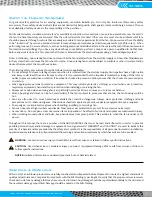
The best means of floor mounting a fan is on a well-designed, flat, level and prepared concrete foundation. The foundation should
have a mass of at least three times that of the supported assembly. Rigid foundation stiffness must be between 1x10
6
lbs./in.
to 4x10
6
lbs./in. depending upon size and speed. The foundation should extend 6" beyond the outer dimensions of the fan and
driver; however, it should be no more than twice the area required for the equipment. If it is made larger, the mass should be
increased accordingly to resist rocking modes of vibration. Anchor bolts should be carefully located by a competent tradesman
as wheel to inlet, bearing location and motor location are critical to final fan alignment. J or T type anchor bolts of sufficient size
should be used and should be tied into the reinforcing bar for the foundation. Pipe sleeves may be incorporated when pouring
the concrete. After the concrete is poured, a pipe sleeve with a diameter of 2 to 2
1
Τ
2
times the anchor bolt diameter should be
provided around the anchor bolt for final adjustment. The mounting surface of the foundation should be smooth for good shim
contact. It may be necessary to grind high spots. When deciding the thickness of the foundation, approximately 1 to 1
1
Τ
2
" height
should be allowed for shimming, grouting, leveling, washers, nuts, etc. The above represents industry best practice. Actual
foundation design should be entrusted to a qualified engineer. Anchor bolts should be accurately placed to coincide with the
predetermined fan securing holes, or the manufactured base, to ensure that the fan is not distorted. (This may impact alignment
and vibration.)
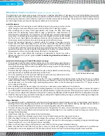
Fans mounted on a sub-floor or mezzanine must have adequate stiffness or be mounted on an inertia base with springs properly
selected. An inertia base is recommended for arrangement 8 fans to ensure alignment of the rotor and drive.
If a structural steel base or platform is to be used, the structure must be designed for the weight of the fan, live loads imposed
by rotation of the rotor and driver, and any external live loads. The structure should be designed to ensure that no natural
frequency will occur within 30% of the fan speed. This is especially true if the structure supports more than one fan. Inertia bases
are generally recommended to provide adequate mass and stiffness for fan operation.
Any ducting should have independent support. Do not use the fan to support ducting as the housing or pedestal may become
distorted. The fan frame can be designed to carry some external loads. Consult the factory if this is a concern. Isolating the fan
from ductwork with flex connections eliminates transmission of vibration. Fans handling hot gases require expansion joints at
both the inlet and discharge to prevent excessive loads caused by thermal growth.
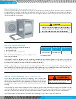
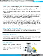
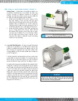
Fan mounted on an inertia base.
Base and pedestal shown filled with reinforced concrete.
WARNING
Refer to handling section prior to lifting equipment.
Summary of Contents for CD-1261
Page 1: ... 0 1 2121 3 4 1 5 6 ...
Page 2: ... ...
Page 3: ... ...
Page 4: ... ...
Page 5: ... ...
Page 6: ... 0 1 2 3 4 5 6 5 6 7 1 1 5 6 5 6 5 6 1 0 0 ...
Page 7: ... ...
Page 8: ... 0 1 2 0 3 0 ...
Page 9: ... ...
Page 10: ... 0 12 2 0 3 4 5 5 5 0 0 ...
Page 11: ... 6 12 0 0 7 5 5 0 8 0 8 5 0 50 9 4 12 0 0 9 4 0 9 64 0 5 0 0 1 0 0 ...
Page 12: ... 0 2 0 0 3 0 6 6 6 6 6 0 0 0 5 5 0 6 0 ...
Page 14: ... ...
Page 15: ... 0 0 1 1 2 1 1 3 0 4 5 1 0 1 0 0 2 1 2 1 0 0 0 2 1 1 1 1 1 0 0 0 1 0 0 0 1 0 1 6 1 1 ...
Page 17: ... 1 0 3 0 0 1 1 1 71 0 0 1 1 1 0 1 1 ...
Page 18: ... ...
Page 25: ... 8 ...
Page 28: ... 1 7 4 0 4 1 4 1 1 4 1 1 1 4 85 4 4 1 4 1 4 0 6 4 1 1 1 01 0 1 4 6 4 1 1 4 L 1 ...
Page 29: ... 4 ...
Page 30: ... 0 1 2 3 24 3 5 6 4 5 6 4 5 5 1 5 4 74 8 5 9 1 4 27 3 5 4 74 8 5 5 29 13 27 3 1 29 13 5 1 ...
Page 31: ... 8 8 80 1 2 3 5 6 4 5 6 4 5 5 1 5 A 9 1 B 4 27 3 888 7 8 0 B 4 C D 5 29 13 B 27 3 888 7 29 13 ...
Page 32: ... 4 24 3 5 6 4 5 6 4 5 5 4 7 M 7 4 7 N 2 0 7 2 M 0 N M ...
Page 35: ... 8 G 8 0 G 4 88 8E 1 2 3 5 6 4 5 6 4 5 5 1 4 1 4 27 3 1 088 7 5 4 1 5 29 13 H 27 3 088 7 ...
Page 36: ... E 5 ...
Page 37: ... 9 4 5 H 0 1 2034 2034 2034 2034 0 5 1 6 71 6 1 2 1 1 1 0 1 81 1 9 9 ...
Page 38: ... 1 5 1 5 1 3 05 3 1 0 1 1 6 A 6 1 A 6 B 1 6 B 6 1 1 1 6 6 6 2 9 0 6 ...
Page 39: ... 0 ...
Page 40: ... 0 0 ...
Page 42: ......
Page 43: ... 0122 3 4 5 6 4 4 4 4 5 4 4 4 4 4 7 7 4 4 6 4 4 5 5 4 5 8 8 3 5 3 5 3 5 3 5 5 ...
Page 44: ... 0 0 0 0 0 0 0 0 0 0 1 1 2 3 0 3 3 0 0 33 0 3 0 3 3 0 ...
Page 46: ... 011 2 3 3 4 3 2 5 5 6 ...
Page 47: ... 011 2 3 4 5 3 6 3 7 7 2 4 ...
Page 48: ... 00 1 2 3 4 3 5 5 5 5 5 3 1 1 2 2 6 1 1 1 5 5 7 5 5 5 5 ...
Page 49: ... 0122 3 4 5 6 7 4 8 4 4 8 4 4 8 5 5 5 5 5 5 5 5 5 5 5 5 ...
Page 50: ... 0 11 2 2 2 2 2 3 4 5 0 5 3 6 7 6 6 8 9 8 9 6 6 8 9 0 1 1 1 1 1 8 9 1 1 1 5 ...
Page 51: ... 011 2 3 4 5 4 2 2 2 6 2 6 6 3 3 3 3 3 3 3 ...
Page 53: ... 011 2 3 4 5 4 2 6 33 2 33 6 6 6 ...
Page 54: ... 011 2 3 3 3 3 4 5 4 33 2 33 6 3 3 3 ...
Page 56: ... 0122 3 4 5 6 7 8 4 4 5 8 4 4 8 9 9 9 8 4 4 4 88 8 8 8 ...
Page 57: ... 0 1 1 1 2 1 3 1 1 1 0 1 1 1 4 1 1 ...
Page 58: ... ...
Page 59: ... ...
Page 96: ...Bearing Maintenance Guide x Lubrication x Troubleshooting ...
Page 97: ......
Page 98: ......
Page 99: ......
Page 100: ......
Page 101: ......
Page 102: ......
Page 103: ......
Page 104: ......
Page 105: ......
Page 106: ......
Page 107: ......
Page 108: ......
Page 109: ......
Page 110: ......
Page 111: ......
Page 112: ......
Page 113: ......
Page 114: ......
Page 115: ......
Page 116: ......
Page 117: ......
Page 118: ......
Page 119: ......
Page 120: ......
Page 121: ......
Page 122: ......
Page 123: ......
Page 124: ......
Page 125: ......
Page 126: ......
Page 165: ... 0 0 1 2 3 4 5 6 52 3 52 3 7 8 4 6 52 4 6 1 9 9 9 9 9 ...
Page 166: ... 0 5 9 9 2 2 4 6 4 6 4 6 7 8 7 8 2 4 6 4 7 8 7 8 2 4 6 4 6 52 A ...
Page 167: ... 0 0 1 2 1 2 3 4 2 1 2 3 4 ...
Page 168: ... 0 2 1 2 3 3 4 2 1 2 3 4 2 ...
Page 194: ......
Page 195: ......
Page 196: ......
Page 218: ......
Page 219: ......
Page 234: ...15 Notes Model 121 Regulators Brochure ...
Page 236: ......


