IM-995
Installation, Operation & Maintenance Manual
20
Optional Accessories (cont.)
Oil Circulation Systems:
a. Use non-detergent, turbine grade oil specified on the general accessory drawing.
b. Utilize the drain ports specified on the general accessory drawing.
c. There must be a slope of 15 degrees or ½" slope per foot to effectively drain the bearing and minimize leakage.
d. Drain lines should be vented at the highest point above the bearing centerline.
e. Piping must be flushed to leave no residue on a 20 micron filter.
f. Return piping should be heat traced to maintain flow in cold conditions.
g. Minimum fan-start oil temperature to be 70° F.
h. Maintain 110-130° F inlet oil temperature during operation.
i. If a heat slinger is supplied, place vanes facing away from the bearing to prevent oil from being drawn out of the bearing.
j. Oil flow must be established by measuring quantity vs time (gpm) at the bearing drain. Too much oil flow can cause
unwanted leakage. Oil flow rate is found on the general assembly drawing.
9. Site-Feed Oilers
— Fans provided with optional, site-feed oilers, the oil level is to be set as indicated by the manufacturer’s
installation instructions provided with the fan.
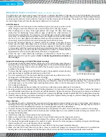
10. Concrete Filled Bases:
Inertia Bases
– Inertia bases are spring isolated bases specifically designed to be filled with concrete (by others). The following
instructions are a guide for filling a base with concrete. Remember to use safe practices when filling concrete into the base. It
is best to fill concrete at or near the base’s final resting area to reduce injury while transferring to the permanent location.
An inertia base is supplied with steel mesh or rebar added within the base frame with the intent of being filled with concrete
and then mounted on springs. Bases may be supplied with or without an optional bottom pan (sealer sheet).
When an optional bottom pan is supplied from the factory, the base must be set on a flat, level surface with the bottom pan
directly on the surface fully supporting the pan to maintain flatness on the bottom side. Pour concrete into the base and
remove excess concrete on the top side of the base to maintain an even mounting surface for fan mounting. Be sure that
the concrete has cured before lifting the base. Install isolators per the isolator installation manual.
When the optional bottom pan is not supplied, the base must be set on a flat, level surface that can fully support the weight
of the concrete. Place a sheet of heavy-mil poly-film between the flat surface and the base frame. Pour concrete into the base
and remove excess concrete on the top side of the base to maintain an even mounting surface for fan mounting. Be sure that
the concrete has cured before lifting the base. Install isolators per the isolator installation manual.
Optional Bottom Pan
Plastic
Sheeting
Click To View Our
Inertia Base Installation Video
Summary of Contents for CD-1261
Page 1: ... 0 1 2121 3 4 1 5 6 ...
Page 2: ... ...
Page 3: ... ...
Page 4: ... ...
Page 5: ... ...
Page 6: ... 0 1 2 3 4 5 6 5 6 7 1 1 5 6 5 6 5 6 1 0 0 ...
Page 7: ... ...
Page 8: ... 0 1 2 0 3 0 ...
Page 9: ... ...
Page 10: ... 0 12 2 0 3 4 5 5 5 0 0 ...
Page 11: ... 6 12 0 0 7 5 5 0 8 0 8 5 0 50 9 4 12 0 0 9 4 0 9 64 0 5 0 0 1 0 0 ...
Page 12: ... 0 2 0 0 3 0 6 6 6 6 6 0 0 0 5 5 0 6 0 ...
Page 14: ... ...
Page 15: ... 0 0 1 1 2 1 1 3 0 4 5 1 0 1 0 0 2 1 2 1 0 0 0 2 1 1 1 1 1 0 0 0 1 0 0 0 1 0 1 6 1 1 ...
Page 17: ... 1 0 3 0 0 1 1 1 71 0 0 1 1 1 0 1 1 ...
Page 18: ... ...
Page 25: ... 8 ...
Page 28: ... 1 7 4 0 4 1 4 1 1 4 1 1 1 4 85 4 4 1 4 1 4 0 6 4 1 1 1 01 0 1 4 6 4 1 1 4 L 1 ...
Page 29: ... 4 ...
Page 30: ... 0 1 2 3 24 3 5 6 4 5 6 4 5 5 1 5 4 74 8 5 9 1 4 27 3 5 4 74 8 5 5 29 13 27 3 1 29 13 5 1 ...
Page 31: ... 8 8 80 1 2 3 5 6 4 5 6 4 5 5 1 5 A 9 1 B 4 27 3 888 7 8 0 B 4 C D 5 29 13 B 27 3 888 7 29 13 ...
Page 32: ... 4 24 3 5 6 4 5 6 4 5 5 4 7 M 7 4 7 N 2 0 7 2 M 0 N M ...
Page 35: ... 8 G 8 0 G 4 88 8E 1 2 3 5 6 4 5 6 4 5 5 1 4 1 4 27 3 1 088 7 5 4 1 5 29 13 H 27 3 088 7 ...
Page 36: ... E 5 ...
Page 37: ... 9 4 5 H 0 1 2034 2034 2034 2034 0 5 1 6 71 6 1 2 1 1 1 0 1 81 1 9 9 ...
Page 38: ... 1 5 1 5 1 3 05 3 1 0 1 1 6 A 6 1 A 6 B 1 6 B 6 1 1 1 6 6 6 2 9 0 6 ...
Page 39: ... 0 ...
Page 40: ... 0 0 ...
Page 42: ......
Page 43: ... 0122 3 4 5 6 4 4 4 4 5 4 4 4 4 4 7 7 4 4 6 4 4 5 5 4 5 8 8 3 5 3 5 3 5 3 5 5 ...
Page 44: ... 0 0 0 0 0 0 0 0 0 0 1 1 2 3 0 3 3 0 0 33 0 3 0 3 3 0 ...
Page 46: ... 011 2 3 3 4 3 2 5 5 6 ...
Page 47: ... 011 2 3 4 5 3 6 3 7 7 2 4 ...
Page 48: ... 00 1 2 3 4 3 5 5 5 5 5 3 1 1 2 2 6 1 1 1 5 5 7 5 5 5 5 ...
Page 49: ... 0122 3 4 5 6 7 4 8 4 4 8 4 4 8 5 5 5 5 5 5 5 5 5 5 5 5 ...
Page 50: ... 0 11 2 2 2 2 2 3 4 5 0 5 3 6 7 6 6 8 9 8 9 6 6 8 9 0 1 1 1 1 1 8 9 1 1 1 5 ...
Page 51: ... 011 2 3 4 5 4 2 2 2 6 2 6 6 3 3 3 3 3 3 3 ...
Page 53: ... 011 2 3 4 5 4 2 6 33 2 33 6 6 6 ...
Page 54: ... 011 2 3 3 3 3 4 5 4 33 2 33 6 3 3 3 ...
Page 56: ... 0122 3 4 5 6 7 8 4 4 5 8 4 4 8 9 9 9 8 4 4 4 88 8 8 8 ...
Page 57: ... 0 1 1 1 2 1 3 1 1 1 0 1 1 1 4 1 1 ...
Page 58: ... ...
Page 59: ... ...
Page 96: ...Bearing Maintenance Guide x Lubrication x Troubleshooting ...
Page 97: ......
Page 98: ......
Page 99: ......
Page 100: ......
Page 101: ......
Page 102: ......
Page 103: ......
Page 104: ......
Page 105: ......
Page 106: ......
Page 107: ......
Page 108: ......
Page 109: ......
Page 110: ......
Page 111: ......
Page 112: ......
Page 113: ......
Page 114: ......
Page 115: ......
Page 116: ......
Page 117: ......
Page 118: ......
Page 119: ......
Page 120: ......
Page 121: ......
Page 122: ......
Page 123: ......
Page 124: ......
Page 125: ......
Page 126: ......
Page 165: ... 0 0 1 2 3 4 5 6 52 3 52 3 7 8 4 6 52 4 6 1 9 9 9 9 9 ...
Page 166: ... 0 5 9 9 2 2 4 6 4 6 4 6 7 8 7 8 2 4 6 4 7 8 7 8 2 4 6 4 6 52 A ...
Page 167: ... 0 0 1 2 1 2 3 4 2 1 2 3 4 ...
Page 168: ... 0 2 1 2 3 3 4 2 1 2 3 4 2 ...
Page 194: ......
Page 195: ......
Page 196: ......
Page 218: ......
Page 219: ......
Page 234: ...15 Notes Model 121 Regulators Brochure ...
Page 236: ......


