8
Model 121 Regulators Brochure
Maximum emergency Pressures
NOTe:
Before using any of the following data, make sure this
entire section is clearly understood.
The maximum pressure the regulator inlet may be subjected
to under abnormal conditions without causing damage to the
regulator is:
¾" through 2½" Pipe Sizes ................................ 70 psi
3" Pipe Size ....................................................... 50 psi
4" Pipe Size ....................................................... 25 psi
The maximum pressure the regulator outlet may be subjected to
without causing damage to the internal parts of the regulator is:
121-8 ................................................. set-point + 5 psi
121-8HP .......................................... set-point + 10 psi
121-12 ............................................... set-point + 5 psi
121-16 ............................................... set-point + 2 psi
6HWSRLQWLVGH¿QHGDVWKHRXWOHWSUHVVXUHDUHJXODWRULVDGMXVWHG
to deliver. If any of the above pressure limits are exceeded, the
regulator must be taken out of service and inspected. Damaged
parts must be repaired or replaced.
The maximum pressure that can be safely contained by the
diaphragm case is:
121-8 ................................................................. 25 psi
121-8HP ............................................................ 25 psi
121-12 ............................................................... 20 psi
121-16 ............................................................... 10 psi
Safely contained means no leakage as well as no bursting.
Over-pressurization Protection
Protect the downstream piping system and the regulator’s low
pressure chambers against over-pressurization due to the
possible regulator malfunction or failure to achieve complete
lockup. The allowable outlet pressure is the lowest of the
maximum pressures permitted by federal codes, state codes,
Sensus bulletin RDS-1498, or other applicable standards. The
method of protection can be a relief valve, monitor regulator,
shutoff device, or similar mechanism.
Full Open Capacity
Capacity of the Model 121 in the full open position can be
calculated using the following formulas and K factors:
1. Q = K
¥
P
0
(P
1
– P
0
................ (for P
1
/P
0
ʘOHVVWKDQ
2. Q =
K P
1
2
............................... (for P
1
/P
0
ʘJUHDWHUWKDQ
4 )XOORSHQFDSDFLW\LQ6&)+RIVSHFL¿FJUDYLW\
natural gas.
P
1
=
absolute
LQOHWSUHVVXUHSVLD
P
0
=
absolute
RXWOHWSUHVVXUHSVLD
3LSH6L]HRXWOHW
........................................ K=1400
1½" Pipe Size ................................................. K=2750
2" Pipe Size .................................................... K=4750
2½" Pipe Size ................................................. K=5250
ó3LSH6L]HRXWOHW
..................................... K=1750
3" Pipe Size .................................................. K=11000
4" Pipe Size .................................................. K=18000
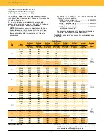
Remember, at the above full open capacities the droop is
VLJQL¿FDQWO\JUHDWHUWKDQVSHFL¿HGLQWKHFDSDFLW\WDEOHVRQ
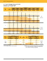
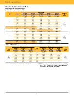
pages 4, 5, 6 and 7.
When checking 121 regulator capacity for use in providing
adequate relief capacity, use the above calculated full open
capacity. Do not use 121 capacity values from the tables on
pages 4, 5, 6 and 7.
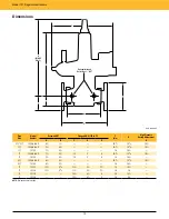
Pipe Sizes
6FUHZHG137
)ODQJHG$16,
125 lb. FF.
¾" x 1"
1½" x 1½"
2" x 2"
¾" x 1¼"
1½" x 2"
3" x 3"
1" x 1"
2" x 2"
4" x 4"
1" x 1¼"
2½" x 2½"
1¼" x 1¼"
3" x 3"
Other gases
Model 121 Regulators are most widely used with natural gas.
However, they perform equally well with LP gas, nitrogen, dry
CO
2
and air.
For other gas capacities, multiply the table values on page 4, 5, 6
and 7 by the applicable correction factors:
7\SHRI*DV
&RUUHFWLRQ)DFWRU
$LU6SHFL¿F*UDYLW\
0.77
3URSDQH6SHFL¿F*UDYLW\
0.63
%783URSDQH$LU0L[6SHFL¿F*UDYLW\
0.71
1LWURJHQ6SHFL¿F*UDYLW\
0.79
'U\&DUERQ'LR[LGH6SHFL¿F*UDYLW\
0.63
For other non-corrosive gases use the following formula:
0.60
CORRECTION FACTOR =
¥
6SHFL¿FJUDYLW\RIWKHJDV
For use with gases not listed above, please contact your Sensus
representative or Industrial Distributor for recommendations.
CAUTION
Turn gas on slowly. If an outlet stop valve is used, it should
EHRSHQHG¿UVW'RQRWRYHUORDGWKHGLDSKUDJPZLWKDVXGGHQ
surge of inlet pressure. Monitor the outlet pressure during
start-up to prevent an outlet pressure overload. ReFeR TO
RM-1328 FOR MORe DeTAIleD START-uP PROCeDuReS.
Summary of Contents for CD-1261
Page 1: ... 0 1 2121 3 4 1 5 6 ...
Page 2: ... ...
Page 3: ... ...
Page 4: ... ...
Page 5: ... ...
Page 6: ... 0 1 2 3 4 5 6 5 6 7 1 1 5 6 5 6 5 6 1 0 0 ...
Page 7: ... ...
Page 8: ... 0 1 2 0 3 0 ...
Page 9: ... ...
Page 10: ... 0 12 2 0 3 4 5 5 5 0 0 ...
Page 11: ... 6 12 0 0 7 5 5 0 8 0 8 5 0 50 9 4 12 0 0 9 4 0 9 64 0 5 0 0 1 0 0 ...
Page 12: ... 0 2 0 0 3 0 6 6 6 6 6 0 0 0 5 5 0 6 0 ...
Page 14: ... ...
Page 15: ... 0 0 1 1 2 1 1 3 0 4 5 1 0 1 0 0 2 1 2 1 0 0 0 2 1 1 1 1 1 0 0 0 1 0 0 0 1 0 1 6 1 1 ...
Page 17: ... 1 0 3 0 0 1 1 1 71 0 0 1 1 1 0 1 1 ...
Page 18: ... ...
Page 25: ... 8 ...
Page 28: ... 1 7 4 0 4 1 4 1 1 4 1 1 1 4 85 4 4 1 4 1 4 0 6 4 1 1 1 01 0 1 4 6 4 1 1 4 L 1 ...
Page 29: ... 4 ...
Page 30: ... 0 1 2 3 24 3 5 6 4 5 6 4 5 5 1 5 4 74 8 5 9 1 4 27 3 5 4 74 8 5 5 29 13 27 3 1 29 13 5 1 ...
Page 31: ... 8 8 80 1 2 3 5 6 4 5 6 4 5 5 1 5 A 9 1 B 4 27 3 888 7 8 0 B 4 C D 5 29 13 B 27 3 888 7 29 13 ...
Page 32: ... 4 24 3 5 6 4 5 6 4 5 5 4 7 M 7 4 7 N 2 0 7 2 M 0 N M ...
Page 35: ... 8 G 8 0 G 4 88 8E 1 2 3 5 6 4 5 6 4 5 5 1 4 1 4 27 3 1 088 7 5 4 1 5 29 13 H 27 3 088 7 ...
Page 36: ... E 5 ...
Page 37: ... 9 4 5 H 0 1 2034 2034 2034 2034 0 5 1 6 71 6 1 2 1 1 1 0 1 81 1 9 9 ...
Page 38: ... 1 5 1 5 1 3 05 3 1 0 1 1 6 A 6 1 A 6 B 1 6 B 6 1 1 1 6 6 6 2 9 0 6 ...
Page 39: ... 0 ...
Page 40: ... 0 0 ...
Page 42: ......
Page 43: ... 0122 3 4 5 6 4 4 4 4 5 4 4 4 4 4 7 7 4 4 6 4 4 5 5 4 5 8 8 3 5 3 5 3 5 3 5 5 ...
Page 44: ... 0 0 0 0 0 0 0 0 0 0 1 1 2 3 0 3 3 0 0 33 0 3 0 3 3 0 ...
Page 46: ... 011 2 3 3 4 3 2 5 5 6 ...
Page 47: ... 011 2 3 4 5 3 6 3 7 7 2 4 ...
Page 48: ... 00 1 2 3 4 3 5 5 5 5 5 3 1 1 2 2 6 1 1 1 5 5 7 5 5 5 5 ...
Page 49: ... 0122 3 4 5 6 7 4 8 4 4 8 4 4 8 5 5 5 5 5 5 5 5 5 5 5 5 ...
Page 50: ... 0 11 2 2 2 2 2 3 4 5 0 5 3 6 7 6 6 8 9 8 9 6 6 8 9 0 1 1 1 1 1 8 9 1 1 1 5 ...
Page 51: ... 011 2 3 4 5 4 2 2 2 6 2 6 6 3 3 3 3 3 3 3 ...
Page 53: ... 011 2 3 4 5 4 2 6 33 2 33 6 6 6 ...
Page 54: ... 011 2 3 3 3 3 4 5 4 33 2 33 6 3 3 3 ...
Page 56: ... 0122 3 4 5 6 7 8 4 4 5 8 4 4 8 9 9 9 8 4 4 4 88 8 8 8 ...
Page 57: ... 0 1 1 1 2 1 3 1 1 1 0 1 1 1 4 1 1 ...
Page 58: ... ...
Page 59: ... ...
Page 96: ...Bearing Maintenance Guide x Lubrication x Troubleshooting ...
Page 97: ......
Page 98: ......
Page 99: ......
Page 100: ......
Page 101: ......
Page 102: ......
Page 103: ......
Page 104: ......
Page 105: ......
Page 106: ......
Page 107: ......
Page 108: ......
Page 109: ......
Page 110: ......
Page 111: ......
Page 112: ......
Page 113: ......
Page 114: ......
Page 115: ......
Page 116: ......
Page 117: ......
Page 118: ......
Page 119: ......
Page 120: ......
Page 121: ......
Page 122: ......
Page 123: ......
Page 124: ......
Page 125: ......
Page 126: ......
Page 165: ... 0 0 1 2 3 4 5 6 52 3 52 3 7 8 4 6 52 4 6 1 9 9 9 9 9 ...
Page 166: ... 0 5 9 9 2 2 4 6 4 6 4 6 7 8 7 8 2 4 6 4 7 8 7 8 2 4 6 4 6 52 A ...
Page 167: ... 0 0 1 2 1 2 3 4 2 1 2 3 4 ...
Page 168: ... 0 2 1 2 3 3 4 2 1 2 3 4 2 ...
Page 194: ......
Page 195: ......
Page 196: ......
Page 218: ......
Page 219: ......
Page 234: ...15 Notes Model 121 Regulators Brochure ...
Page 236: ......


