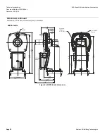
SKPx5.xxxUx
Electro
Ͳ
hydraulic
actuators
Technical
Instructions
Document
Number
CC1N7643us
December
10,
2018
Siemens
AG
Building
Technologies
Page
9
Specifications
Continued
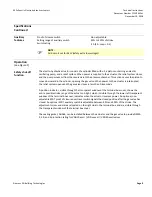
Auxiliary
Proof
of
closure
switch
Non
Ͳ
adjustable
features
Setting
range
of
auxiliary
switch
40%
to
100%
of
stroke
Switch
rating
4
A
(2
A,
cos
M
=
0.3)
)
NOTE:
AUX
Ͳ
circuit
not
for
SELV
(safety
extra
low
voltage)!
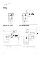
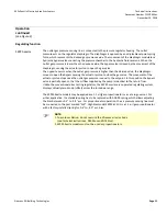
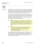
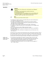
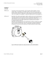
Operation
(see
Figure
1)
Safety
shut
Ͳ
off
function
The
electro
Ͳ
hydraulic
actuator
consists
of
a
cylinder
filled
with
oil,
a
piston
containing
an
electric
oscillating
pump,
and
a
relief
system.
When
power
is
supplied
to
the
actuator,
the
relief
system
closes,
and
the
pump
moves
oil
from
the
reservoir
into
the
pressure
chamber.
This
action
causes
the
piston
to
move
downward
in
the
cylinder,
opening
the
gas
valve.
When
power
to
the
actuator
is
interrupted,
the
relief
system
opens
and
the
gas
valve
closes
in
less
than
0.8
seconds.
A
position
indicator,
visible
through
the
transparent
window
of
the
terminal
box
cover,
shows
the
entire
possible
stroke
range
of
the
actuator.
A
light,
which
is
visible
through
the
lower
left
transparent
window
of
the
terminal
box
cover,
indicates
when
the
actuator
receives
power.
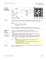
An
optional,
non
Ͳ
adjustable
SPDT
proof
of
closure
over
travel
switch
signals
the
closed
position
after
the
gas
valve
has
closed.
An
optional
SPDT
auxiliary
switch
is
adjustable
between
40%
and
100%
of
the
stroke.
The
adjustment
screw
and
scale
are
located
on
the
right
side
in
the
terminal
box,
and
are
visible
through
the
transparent
window
of
the
terminal
box
cover.
The
sealing
gasket,
AGA66,
can
be
installed
between
the
actuator
and
the
gas
valve
to
provide
NEMA
3,
3R,
and
4
protection
rating
for
VGG10.xxxU
/
VGDxx.xxxU
/
VRD40.xxxU
valves.
Summary of Contents for CD-1261
Page 1: ... 0 1 2121 3 4 1 5 6 ...
Page 2: ... ...
Page 3: ... ...
Page 4: ... ...
Page 5: ... ...
Page 6: ... 0 1 2 3 4 5 6 5 6 7 1 1 5 6 5 6 5 6 1 0 0 ...
Page 7: ... ...
Page 8: ... 0 1 2 0 3 0 ...
Page 9: ... ...
Page 10: ... 0 12 2 0 3 4 5 5 5 0 0 ...
Page 11: ... 6 12 0 0 7 5 5 0 8 0 8 5 0 50 9 4 12 0 0 9 4 0 9 64 0 5 0 0 1 0 0 ...
Page 12: ... 0 2 0 0 3 0 6 6 6 6 6 0 0 0 5 5 0 6 0 ...
Page 14: ... ...
Page 15: ... 0 0 1 1 2 1 1 3 0 4 5 1 0 1 0 0 2 1 2 1 0 0 0 2 1 1 1 1 1 0 0 0 1 0 0 0 1 0 1 6 1 1 ...
Page 17: ... 1 0 3 0 0 1 1 1 71 0 0 1 1 1 0 1 1 ...
Page 18: ... ...
Page 25: ... 8 ...
Page 28: ... 1 7 4 0 4 1 4 1 1 4 1 1 1 4 85 4 4 1 4 1 4 0 6 4 1 1 1 01 0 1 4 6 4 1 1 4 L 1 ...
Page 29: ... 4 ...
Page 30: ... 0 1 2 3 24 3 5 6 4 5 6 4 5 5 1 5 4 74 8 5 9 1 4 27 3 5 4 74 8 5 5 29 13 27 3 1 29 13 5 1 ...
Page 31: ... 8 8 80 1 2 3 5 6 4 5 6 4 5 5 1 5 A 9 1 B 4 27 3 888 7 8 0 B 4 C D 5 29 13 B 27 3 888 7 29 13 ...
Page 32: ... 4 24 3 5 6 4 5 6 4 5 5 4 7 M 7 4 7 N 2 0 7 2 M 0 N M ...
Page 35: ... 8 G 8 0 G 4 88 8E 1 2 3 5 6 4 5 6 4 5 5 1 4 1 4 27 3 1 088 7 5 4 1 5 29 13 H 27 3 088 7 ...
Page 36: ... E 5 ...
Page 37: ... 9 4 5 H 0 1 2034 2034 2034 2034 0 5 1 6 71 6 1 2 1 1 1 0 1 81 1 9 9 ...
Page 38: ... 1 5 1 5 1 3 05 3 1 0 1 1 6 A 6 1 A 6 B 1 6 B 6 1 1 1 6 6 6 2 9 0 6 ...
Page 39: ... 0 ...
Page 40: ... 0 0 ...
Page 42: ......
Page 43: ... 0122 3 4 5 6 4 4 4 4 5 4 4 4 4 4 7 7 4 4 6 4 4 5 5 4 5 8 8 3 5 3 5 3 5 3 5 5 ...
Page 44: ... 0 0 0 0 0 0 0 0 0 0 1 1 2 3 0 3 3 0 0 33 0 3 0 3 3 0 ...
Page 46: ... 011 2 3 3 4 3 2 5 5 6 ...
Page 47: ... 011 2 3 4 5 3 6 3 7 7 2 4 ...
Page 48: ... 00 1 2 3 4 3 5 5 5 5 5 3 1 1 2 2 6 1 1 1 5 5 7 5 5 5 5 ...
Page 49: ... 0122 3 4 5 6 7 4 8 4 4 8 4 4 8 5 5 5 5 5 5 5 5 5 5 5 5 ...
Page 50: ... 0 11 2 2 2 2 2 3 4 5 0 5 3 6 7 6 6 8 9 8 9 6 6 8 9 0 1 1 1 1 1 8 9 1 1 1 5 ...
Page 51: ... 011 2 3 4 5 4 2 2 2 6 2 6 6 3 3 3 3 3 3 3 ...
Page 53: ... 011 2 3 4 5 4 2 6 33 2 33 6 6 6 ...
Page 54: ... 011 2 3 3 3 3 4 5 4 33 2 33 6 3 3 3 ...
Page 56: ... 0122 3 4 5 6 7 8 4 4 5 8 4 4 8 9 9 9 8 4 4 4 88 8 8 8 ...
Page 57: ... 0 1 1 1 2 1 3 1 1 1 0 1 1 1 4 1 1 ...
Page 58: ... ...
Page 59: ... ...
Page 96: ...Bearing Maintenance Guide x Lubrication x Troubleshooting ...
Page 97: ......
Page 98: ......
Page 99: ......
Page 100: ......
Page 101: ......
Page 102: ......
Page 103: ......
Page 104: ......
Page 105: ......
Page 106: ......
Page 107: ......
Page 108: ......
Page 109: ......
Page 110: ......
Page 111: ......
Page 112: ......
Page 113: ......
Page 114: ......
Page 115: ......
Page 116: ......
Page 117: ......
Page 118: ......
Page 119: ......
Page 120: ......
Page 121: ......
Page 122: ......
Page 123: ......
Page 124: ......
Page 125: ......
Page 126: ......
Page 165: ... 0 0 1 2 3 4 5 6 52 3 52 3 7 8 4 6 52 4 6 1 9 9 9 9 9 ...
Page 166: ... 0 5 9 9 2 2 4 6 4 6 4 6 7 8 7 8 2 4 6 4 7 8 7 8 2 4 6 4 6 52 A ...
Page 167: ... 0 0 1 2 1 2 3 4 2 1 2 3 4 ...
Page 168: ... 0 2 1 2 3 3 4 2 1 2 3 4 2 ...
Page 194: ......
Page 195: ......
Page 196: ......
Page 218: ......
Page 219: ......
Page 234: ...15 Notes Model 121 Regulators Brochure ...
Page 236: ......


