SKPx5.xxxUx
Electro
Ͳ
hydraulic
actuators
Technical
Instructions
Document
Number
CC1N7643us
December
10,
2018
Siemens
AG
Building
Technologies
Page
13
Operation
continued
(see
Figure
4)
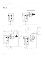
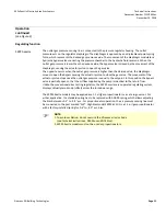
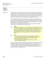
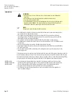
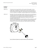
SKP75.xxxUx
During
the
burner
pre
Ͳ
purge
period,
when
the
gas
valve
is
closed,
only
the
air
pressure
acts
on
the
regulator.
This
causes
the
air
diaphragm
to
move
to
the
left
and
close
the
regulating
hydraulic
bypass
valve.
When
the
actuator
is
powered,
the
gas
valve
begins
to
open.
The
downstream
gas
pressure
immediately
begins
to
increase
until
the
downstream
gas
pressure
is
in
balance
with
the
air
pressure
(in
accordance
with
the
pressure
ratio
adjusted
on
the
regulator).
The
bypass
valve
is
now
partially
open
so
that
the
oil
flow
supplied
by
the
pump
is
identical
to
the
return
flow.
If,
for
example,
heat
demand
increases,
the
air
damper
would
open
further
increasing
the
air
pressure.
The
air
diaphragm
would
move
to
the
left,
causing
the
bypass
valve
to
close
and
the
gas
valve
to
open
further.
The
opening
of
the
gas
valve
increases
the
downstream
gas
pressure
moving
the
gas
diaphragm
to
the
right
until
balance
is
restored
and
the
flow
supplied
by
the
pump
is
once
again
identical
to
the
return
flow
through
the
regulator
bypass.
Unlike
conventional
direct
acting
regulators
the
SKP75.xxxUx
servo
operated
regulating
system
displays
virtually
zero
droop
(offset)
across
the
turndown
range.
The
gas
to
air
pressure
ratio
is
adjustable
from
0.4:1
to
9:1.
The
setting
is
visible
through
a
window
in
the
regulator.
Once
set,
the
gas
to
air
pressure
ratio
remains
constant
over
the
entire
output
range.
The
gas
to
air
flow
ratio
will
remain
constant
(if
the
cross
sections
of
the
air
and
gas
orifices
in
the
burner
head
are
fixed).
The
SKP75.xxxUx
is
not
recommended
for
use
with
burners
incorporating
a
sliding
/
continuously
adjustable
head
arrangement.
Many
burner
designs,
because
of
reduced
mixing
energy
at
the
low
fire
level,
require
increased
excess
air
at
low
fire
in
order
to
maintain
optimum
combustion
parameters.
To
accommodate
this
requirement
the
SKP75.xxxUx
incorporates
a
bias
adjustment,
which
allows
the
characteristic
of
the
regulator
to
be
displaced
either
towards
excess
air
or
reduced
air.
Pressure
fluctuations
in
the
combustion
chamber
do
not
influence
the
performance
of
the
SKP75.xxxUx
air/gas
ratio
controller.
There
is
no
need
for
any
compensation
circuit.
)
NOTE:
To
avoid
oscillation,
do
not
oversize
the
VGxxx.xxxU
valves
(see
Technical
Instructions
,
N7636us
and
N7631us).
Summary of Contents for CD-1261
Page 1: ... 0 1 2121 3 4 1 5 6 ...
Page 2: ... ...
Page 3: ... ...
Page 4: ... ...
Page 5: ... ...
Page 6: ... 0 1 2 3 4 5 6 5 6 7 1 1 5 6 5 6 5 6 1 0 0 ...
Page 7: ... ...
Page 8: ... 0 1 2 0 3 0 ...
Page 9: ... ...
Page 10: ... 0 12 2 0 3 4 5 5 5 0 0 ...
Page 11: ... 6 12 0 0 7 5 5 0 8 0 8 5 0 50 9 4 12 0 0 9 4 0 9 64 0 5 0 0 1 0 0 ...
Page 12: ... 0 2 0 0 3 0 6 6 6 6 6 0 0 0 5 5 0 6 0 ...
Page 14: ... ...
Page 15: ... 0 0 1 1 2 1 1 3 0 4 5 1 0 1 0 0 2 1 2 1 0 0 0 2 1 1 1 1 1 0 0 0 1 0 0 0 1 0 1 6 1 1 ...
Page 17: ... 1 0 3 0 0 1 1 1 71 0 0 1 1 1 0 1 1 ...
Page 18: ... ...
Page 25: ... 8 ...
Page 28: ... 1 7 4 0 4 1 4 1 1 4 1 1 1 4 85 4 4 1 4 1 4 0 6 4 1 1 1 01 0 1 4 6 4 1 1 4 L 1 ...
Page 29: ... 4 ...
Page 30: ... 0 1 2 3 24 3 5 6 4 5 6 4 5 5 1 5 4 74 8 5 9 1 4 27 3 5 4 74 8 5 5 29 13 27 3 1 29 13 5 1 ...
Page 31: ... 8 8 80 1 2 3 5 6 4 5 6 4 5 5 1 5 A 9 1 B 4 27 3 888 7 8 0 B 4 C D 5 29 13 B 27 3 888 7 29 13 ...
Page 32: ... 4 24 3 5 6 4 5 6 4 5 5 4 7 M 7 4 7 N 2 0 7 2 M 0 N M ...
Page 35: ... 8 G 8 0 G 4 88 8E 1 2 3 5 6 4 5 6 4 5 5 1 4 1 4 27 3 1 088 7 5 4 1 5 29 13 H 27 3 088 7 ...
Page 36: ... E 5 ...
Page 37: ... 9 4 5 H 0 1 2034 2034 2034 2034 0 5 1 6 71 6 1 2 1 1 1 0 1 81 1 9 9 ...
Page 38: ... 1 5 1 5 1 3 05 3 1 0 1 1 6 A 6 1 A 6 B 1 6 B 6 1 1 1 6 6 6 2 9 0 6 ...
Page 39: ... 0 ...
Page 40: ... 0 0 ...
Page 42: ......
Page 43: ... 0122 3 4 5 6 4 4 4 4 5 4 4 4 4 4 7 7 4 4 6 4 4 5 5 4 5 8 8 3 5 3 5 3 5 3 5 5 ...
Page 44: ... 0 0 0 0 0 0 0 0 0 0 1 1 2 3 0 3 3 0 0 33 0 3 0 3 3 0 ...
Page 46: ... 011 2 3 3 4 3 2 5 5 6 ...
Page 47: ... 011 2 3 4 5 3 6 3 7 7 2 4 ...
Page 48: ... 00 1 2 3 4 3 5 5 5 5 5 3 1 1 2 2 6 1 1 1 5 5 7 5 5 5 5 ...
Page 49: ... 0122 3 4 5 6 7 4 8 4 4 8 4 4 8 5 5 5 5 5 5 5 5 5 5 5 5 ...
Page 50: ... 0 11 2 2 2 2 2 3 4 5 0 5 3 6 7 6 6 8 9 8 9 6 6 8 9 0 1 1 1 1 1 8 9 1 1 1 5 ...
Page 51: ... 011 2 3 4 5 4 2 2 2 6 2 6 6 3 3 3 3 3 3 3 ...
Page 53: ... 011 2 3 4 5 4 2 6 33 2 33 6 6 6 ...
Page 54: ... 011 2 3 3 3 3 4 5 4 33 2 33 6 3 3 3 ...
Page 56: ... 0122 3 4 5 6 7 8 4 4 5 8 4 4 8 9 9 9 8 4 4 4 88 8 8 8 ...
Page 57: ... 0 1 1 1 2 1 3 1 1 1 0 1 1 1 4 1 1 ...
Page 58: ... ...
Page 59: ... ...
Page 96: ...Bearing Maintenance Guide x Lubrication x Troubleshooting ...
Page 97: ......
Page 98: ......
Page 99: ......
Page 100: ......
Page 101: ......
Page 102: ......
Page 103: ......
Page 104: ......
Page 105: ......
Page 106: ......
Page 107: ......
Page 108: ......
Page 109: ......
Page 110: ......
Page 111: ......
Page 112: ......
Page 113: ......
Page 114: ......
Page 115: ......
Page 116: ......
Page 117: ......
Page 118: ......
Page 119: ......
Page 120: ......
Page 121: ......
Page 122: ......
Page 123: ......
Page 124: ......
Page 125: ......
Page 126: ......
Page 165: ... 0 0 1 2 3 4 5 6 52 3 52 3 7 8 4 6 52 4 6 1 9 9 9 9 9 ...
Page 166: ... 0 5 9 9 2 2 4 6 4 6 4 6 7 8 7 8 2 4 6 4 7 8 7 8 2 4 6 4 6 52 A ...
Page 167: ... 0 0 1 2 1 2 3 4 2 1 2 3 4 ...
Page 168: ... 0 2 1 2 3 3 4 2 1 2 3 4 2 ...
Page 194: ......
Page 195: ......
Page 196: ......
Page 218: ......
Page 219: ......
Page 234: ...15 Notes Model 121 Regulators Brochure ...
Page 236: ......

