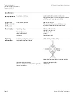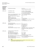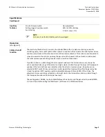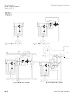
Technical
Instructions
SKPx5.xxxUx
Electro
Ͳ
hydraulic
actuators
Document
Number
CC1N7643us
December
10,
2018
Page
14
Siemens
AG
Building
Technologies
Installation
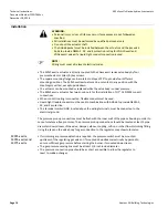
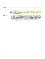
WARNING:
•
Personal
injury
or
loss
of
life
may
occur
if
procedures
are
not
followed
as
specified.
•
All
installations
must
be
performed
by
qualified
personnel
only.
•
Do
not
pull
the
actuator
shaft.
•
The
AGA66
gasket
must
be
installed
between
the
actuator
and
the
gas
valve
body
to
provide
NEMA
3,
3R,
and
4
protection
rating
for
VGG10.xxxU
and
VGDxx.xxxU
valves
if
a
liquid
Ͳ
tight
conduit
connection
is
used.
)
NOTE:
Wiring
must
meet
all
relevant
electrical
codes.
•
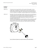
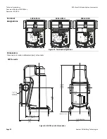
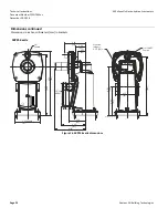
The
SKPx5.xxxUx
actuator
is
directly
coupled
to
the
VGxxx.xxxU
series
valve
body
by
four
premounted
4
mm
Allen
(R)
key
screws.
•
The
square
mounting
flange
can
be
rotated
in
steps
of
90°
to
provide
four
different
mounting
positions.
The
SKPx5.xxxUx
actuator
can
be
mounted
in
any
position
with
the
diaphragms
vertical,
except
upside
down.
•
The
actuator
can
be
mounted
or
replaced
while
the
valve
body
is
under
pressure.
•
The
SKPx5.xxxUx
actuator
has
two
knock
Ͳ
outs
for
the
installation
of
1/2”
Ͳ
14
NPSM
conduit
connections.
•
When
conduit
routing
is
connected,
flexible
conduit
must
be
used.
•
Liquid
tight
flexible
conduit
must
be
used
in
combination
with
AGA66
to
provide
NEMA
3,
3R,
and
4
protection.
•
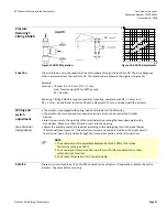
The
terminal
marked
GND,
located
above
the
wiring
terminals,
must
be
connected
to
the
electrical
ground.
The
pressure
pick
Ͳ
up
connections
must
be
flush
with
the
inner
wall
of
the
pipe
or
housing
in
order
to
sense
turbulence
Ͳ
free
pressures.
The
pressure
pick
Ͳ
up
connections
should
be
located
at
least
5
pipe
diameters
downstream
of
the
valve,
damper,
elbow,
coupling,
orifice,
or
other
flow
disturbing
fitting.
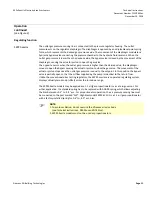
Using
the
taps
on
the
valve
body
for
gas
connection
to
the
regulator
may
show
turbulence.
SKP25.xxxUx,
SKP55.xxxUx
and
SKP75.xxxUx
•
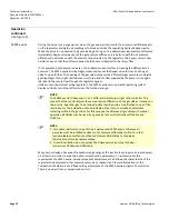
If
minimum
gas
pressure
detection
is
required,
the
pressure
switch
must
be
mounted
upstream
of
the
regulating
gas
valve
or
if
mounted
downstream
electrically
by
Ͳ
passed
to
ensure
sufficient
gas
pressure
before
starting
the
burner.
If
mounted
downstream.
•
The
gas
pressure
sensing
line
must
be
at
least
1/4
Ͳ
inch
inside
diameter.
•
The
pressure
connection
pipe
should
be
as
short
as
possible
to
allow
the
regulator
to
react
to
sudden
changes.
Summary of Contents for CD-1261
Page 1: ... 0 1 2121 3 4 1 5 6 ...
Page 2: ... ...
Page 3: ... ...
Page 4: ... ...
Page 5: ... ...
Page 6: ... 0 1 2 3 4 5 6 5 6 7 1 1 5 6 5 6 5 6 1 0 0 ...
Page 7: ... ...
Page 8: ... 0 1 2 0 3 0 ...
Page 9: ... ...
Page 10: ... 0 12 2 0 3 4 5 5 5 0 0 ...
Page 11: ... 6 12 0 0 7 5 5 0 8 0 8 5 0 50 9 4 12 0 0 9 4 0 9 64 0 5 0 0 1 0 0 ...
Page 12: ... 0 2 0 0 3 0 6 6 6 6 6 0 0 0 5 5 0 6 0 ...
Page 14: ... ...
Page 15: ... 0 0 1 1 2 1 1 3 0 4 5 1 0 1 0 0 2 1 2 1 0 0 0 2 1 1 1 1 1 0 0 0 1 0 0 0 1 0 1 6 1 1 ...
Page 17: ... 1 0 3 0 0 1 1 1 71 0 0 1 1 1 0 1 1 ...
Page 18: ... ...
Page 25: ... 8 ...
Page 28: ... 1 7 4 0 4 1 4 1 1 4 1 1 1 4 85 4 4 1 4 1 4 0 6 4 1 1 1 01 0 1 4 6 4 1 1 4 L 1 ...
Page 29: ... 4 ...
Page 30: ... 0 1 2 3 24 3 5 6 4 5 6 4 5 5 1 5 4 74 8 5 9 1 4 27 3 5 4 74 8 5 5 29 13 27 3 1 29 13 5 1 ...
Page 31: ... 8 8 80 1 2 3 5 6 4 5 6 4 5 5 1 5 A 9 1 B 4 27 3 888 7 8 0 B 4 C D 5 29 13 B 27 3 888 7 29 13 ...
Page 32: ... 4 24 3 5 6 4 5 6 4 5 5 4 7 M 7 4 7 N 2 0 7 2 M 0 N M ...
Page 35: ... 8 G 8 0 G 4 88 8E 1 2 3 5 6 4 5 6 4 5 5 1 4 1 4 27 3 1 088 7 5 4 1 5 29 13 H 27 3 088 7 ...
Page 36: ... E 5 ...
Page 37: ... 9 4 5 H 0 1 2034 2034 2034 2034 0 5 1 6 71 6 1 2 1 1 1 0 1 81 1 9 9 ...
Page 38: ... 1 5 1 5 1 3 05 3 1 0 1 1 6 A 6 1 A 6 B 1 6 B 6 1 1 1 6 6 6 2 9 0 6 ...
Page 39: ... 0 ...
Page 40: ... 0 0 ...
Page 42: ......
Page 43: ... 0122 3 4 5 6 4 4 4 4 5 4 4 4 4 4 7 7 4 4 6 4 4 5 5 4 5 8 8 3 5 3 5 3 5 3 5 5 ...
Page 44: ... 0 0 0 0 0 0 0 0 0 0 1 1 2 3 0 3 3 0 0 33 0 3 0 3 3 0 ...
Page 46: ... 011 2 3 3 4 3 2 5 5 6 ...
Page 47: ... 011 2 3 4 5 3 6 3 7 7 2 4 ...
Page 48: ... 00 1 2 3 4 3 5 5 5 5 5 3 1 1 2 2 6 1 1 1 5 5 7 5 5 5 5 ...
Page 49: ... 0122 3 4 5 6 7 4 8 4 4 8 4 4 8 5 5 5 5 5 5 5 5 5 5 5 5 ...
Page 50: ... 0 11 2 2 2 2 2 3 4 5 0 5 3 6 7 6 6 8 9 8 9 6 6 8 9 0 1 1 1 1 1 8 9 1 1 1 5 ...
Page 51: ... 011 2 3 4 5 4 2 2 2 6 2 6 6 3 3 3 3 3 3 3 ...
Page 53: ... 011 2 3 4 5 4 2 6 33 2 33 6 6 6 ...
Page 54: ... 011 2 3 3 3 3 4 5 4 33 2 33 6 3 3 3 ...
Page 56: ... 0122 3 4 5 6 7 8 4 4 5 8 4 4 8 9 9 9 8 4 4 4 88 8 8 8 ...
Page 57: ... 0 1 1 1 2 1 3 1 1 1 0 1 1 1 4 1 1 ...
Page 58: ... ...
Page 59: ... ...
Page 96: ...Bearing Maintenance Guide x Lubrication x Troubleshooting ...
Page 97: ......
Page 98: ......
Page 99: ......
Page 100: ......
Page 101: ......
Page 102: ......
Page 103: ......
Page 104: ......
Page 105: ......
Page 106: ......
Page 107: ......
Page 108: ......
Page 109: ......
Page 110: ......
Page 111: ......
Page 112: ......
Page 113: ......
Page 114: ......
Page 115: ......
Page 116: ......
Page 117: ......
Page 118: ......
Page 119: ......
Page 120: ......
Page 121: ......
Page 122: ......
Page 123: ......
Page 124: ......
Page 125: ......
Page 126: ......
Page 165: ... 0 0 1 2 3 4 5 6 52 3 52 3 7 8 4 6 52 4 6 1 9 9 9 9 9 ...
Page 166: ... 0 5 9 9 2 2 4 6 4 6 4 6 7 8 7 8 2 4 6 4 7 8 7 8 2 4 6 4 6 52 A ...
Page 167: ... 0 0 1 2 1 2 3 4 2 1 2 3 4 ...
Page 168: ... 0 2 1 2 3 3 4 2 1 2 3 4 2 ...
Page 194: ......
Page 195: ......
Page 196: ......
Page 218: ......
Page 219: ......
Page 234: ...15 Notes Model 121 Regulators Brochure ...
Page 236: ......


