Rexnord
®
Planetgear™ 7000 Series Speed Reducer
s
Owners Manual
Sizes Neptune, Neptune Plus, Orion Plus, Saturn Plus & Titan Plus (Page 5 of 32)
Rexnord
158-170
3001 W. Canal St., Milwaukee, WI 53208-4200
January 2015
Telephone: 414-937-4359 Fax: 414-937-4359 www.rexnord.com
Supersedes 11-12
2.3.1b. MOTORS (C-FACE & IEC MOTOR
FLANGE UNITS) – Neptune, Neptune Plus,
& Orion Plus Quad/Quint Only
1. Mount the reducer C-face coupling or IEC motor flange
coupling onto the motor shaft with the appropriate size
key. The motor shaft to coupling fit should be snug
and may require light tapping (
NOTE
: Warming up
the coupling and applying an Anti-seize compound to
the motor shaft is helpful).
NOTE
: A loose fit coupling
should be avoided and a heavy fit could damage motor
bearings if the coupling is pressed onto the motor shaft
with extreme force.
CAUTION
: Never turn down the motor shaft diameter
to allow for easy coupling installation, as this will cause
coupling movement and wear during operation.
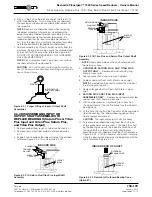
2.a. C-FACE: Locate the C-Face coupling 0.688 to 0.750” from
the motor face (Hint: Standard keystock is helpful for this
purpose). Refer to the illustration in Figure 2.3.1 b.
0.500”
0.625”
DOUBLE
LIPPED
SEAL
(NEPTUNE
QUADRUPLE/QUINTUPLE)
HOLD DIMENSION WHEN
MOUNTING INPUT
COUPLING TO
MOTOR SHAFT
SETSCREWS
C-FACE COUPLING
REDUCER
INPUT GEAR
Figure 2.3.1b C-Face Cross Section
INTEGRAL
HUB SEAL
INTERGAL
COUPLING
INPUT
GEAR
THRUST
WASHER (2)
THRUST
BEARING
SEEP HOLE MUST BE MOUNTED
IN THE 6 O’CLOCK POSITION
13 mm
15 mm
HOLD DIMENSIONS WHEN
MOUNTING INPUT COUPLING
TO MOTOR SHAFT
MOTOR
SHAFT
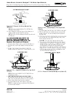
Figure 2.3.1c IEC Cross Section
3. Tighten the coupling set screws; one located over
the key and the other located at 90° (degrees). After
tightening the set screws, the gap between the motor
face and the coupling should be measured again to
insure that the tolerance has been maintained. If the
tolerance is not within the specification, loosen the set
screws and repeat steps 2 and 3.
4. Mount the motor with coupling to the reducer. Align the
internal spline end of the coupling with the external
spline end of the reducer input gear.
PARALLEL MISALIGNMENT
ANGULAR MISALIGNMENT
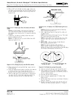
Figure 2.3.2 Parallel and Angular Misalignment
CAUTION
: Be careful not to roll the seal when installing
or removing the coupling and motor. This could result in
oil leakage during operation.
5. Align the mounting holes of the motor with the mounting
holes of the reducer, and fasten, reference Table 17
(Page 28) for recommended bolt torques.
2.3.2 COUPLINGS
Mount the reducer coupling hub on the input shaft and the
motor coupling hub on the motor shaft as instructed in the
manual shipped with the coupling. If the coupling is not a
Rexnord® Omega®, refer to the manufacturers literature
for installation instructions. If Rexnord does not mount
the motor, the couplings are mounted for shipment only.
Coupling bolts and coupling instructions are packed inside
the coupling elements. Note: Prior to the installation of the
element, check both coupling hubs for the required parallel
and angular alignment; Reference Figure 2.3.2.
MOTOR
THREADED
SUPPORT
BOLTS
REDUCER
REDUCER
FAN/SHROUD
GUARD
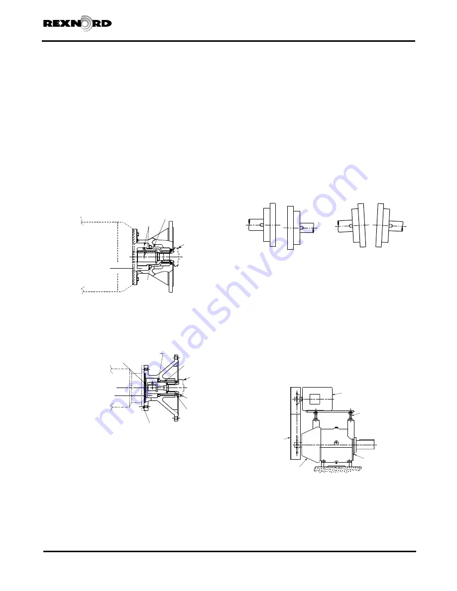
Figure 2.3.3 Planetgear 7000 Top Motor Mount
2.b. IEC MOTOR FLANGE COUPLING: Locate the coupling
13.0 to 14.0mm from the motor face. Refer to the
illustration in Figure 2.3.1 c.
2.3.3 SPROCKETS OR SHEAVES
Prior to installing sprockets or sheaves, review the
manufacturers requirements for chain or belt tension and
required alignment. When mounting the sprocket or sheave to
the shaft, locate it as close as possible to the reducer. This will
minimize the overhung load and prolong bearing life.
When using a Planetgear 7000 top motor mount accessory,
the belt tension can be changed by varying the height of
the motor mount plate. This can be done by adjusting the
four threaded support bolts. Reference Figure 2.3.3.
NOTE
: Mount sheaves and belts as close to the reducer as
possible to avoid undue overhung loading on the bearings.
Summary of Contents for CD-1261
Page 1: ... 0 1 2121 3 4 1 5 6 ...
Page 2: ... ...
Page 3: ... ...
Page 4: ... ...
Page 5: ... ...
Page 6: ... 0 1 2 3 4 5 6 5 6 7 1 1 5 6 5 6 5 6 1 0 0 ...
Page 7: ... ...
Page 8: ... 0 1 2 0 3 0 ...
Page 9: ... ...
Page 10: ... 0 12 2 0 3 4 5 5 5 0 0 ...
Page 11: ... 6 12 0 0 7 5 5 0 8 0 8 5 0 50 9 4 12 0 0 9 4 0 9 64 0 5 0 0 1 0 0 ...
Page 12: ... 0 2 0 0 3 0 6 6 6 6 6 0 0 0 5 5 0 6 0 ...
Page 14: ... ...
Page 15: ... 0 0 1 1 2 1 1 3 0 4 5 1 0 1 0 0 2 1 2 1 0 0 0 2 1 1 1 1 1 0 0 0 1 0 0 0 1 0 1 6 1 1 ...
Page 17: ... 1 0 3 0 0 1 1 1 71 0 0 1 1 1 0 1 1 ...
Page 18: ... ...
Page 25: ... 8 ...
Page 28: ... 1 7 4 0 4 1 4 1 1 4 1 1 1 4 85 4 4 1 4 1 4 0 6 4 1 1 1 01 0 1 4 6 4 1 1 4 L 1 ...
Page 29: ... 4 ...
Page 30: ... 0 1 2 3 24 3 5 6 4 5 6 4 5 5 1 5 4 74 8 5 9 1 4 27 3 5 4 74 8 5 5 29 13 27 3 1 29 13 5 1 ...
Page 31: ... 8 8 80 1 2 3 5 6 4 5 6 4 5 5 1 5 A 9 1 B 4 27 3 888 7 8 0 B 4 C D 5 29 13 B 27 3 888 7 29 13 ...
Page 32: ... 4 24 3 5 6 4 5 6 4 5 5 4 7 M 7 4 7 N 2 0 7 2 M 0 N M ...
Page 35: ... 8 G 8 0 G 4 88 8E 1 2 3 5 6 4 5 6 4 5 5 1 4 1 4 27 3 1 088 7 5 4 1 5 29 13 H 27 3 088 7 ...
Page 36: ... E 5 ...
Page 37: ... 9 4 5 H 0 1 2034 2034 2034 2034 0 5 1 6 71 6 1 2 1 1 1 0 1 81 1 9 9 ...
Page 38: ... 1 5 1 5 1 3 05 3 1 0 1 1 6 A 6 1 A 6 B 1 6 B 6 1 1 1 6 6 6 2 9 0 6 ...
Page 39: ... 0 ...
Page 40: ... 0 0 ...
Page 42: ......
Page 43: ... 0122 3 4 5 6 4 4 4 4 5 4 4 4 4 4 7 7 4 4 6 4 4 5 5 4 5 8 8 3 5 3 5 3 5 3 5 5 ...
Page 44: ... 0 0 0 0 0 0 0 0 0 0 1 1 2 3 0 3 3 0 0 33 0 3 0 3 3 0 ...
Page 46: ... 011 2 3 3 4 3 2 5 5 6 ...
Page 47: ... 011 2 3 4 5 3 6 3 7 7 2 4 ...
Page 48: ... 00 1 2 3 4 3 5 5 5 5 5 3 1 1 2 2 6 1 1 1 5 5 7 5 5 5 5 ...
Page 49: ... 0122 3 4 5 6 7 4 8 4 4 8 4 4 8 5 5 5 5 5 5 5 5 5 5 5 5 ...
Page 50: ... 0 11 2 2 2 2 2 3 4 5 0 5 3 6 7 6 6 8 9 8 9 6 6 8 9 0 1 1 1 1 1 8 9 1 1 1 5 ...
Page 51: ... 011 2 3 4 5 4 2 2 2 6 2 6 6 3 3 3 3 3 3 3 ...
Page 53: ... 011 2 3 4 5 4 2 6 33 2 33 6 6 6 ...
Page 54: ... 011 2 3 3 3 3 4 5 4 33 2 33 6 3 3 3 ...
Page 56: ... 0122 3 4 5 6 7 8 4 4 5 8 4 4 8 9 9 9 8 4 4 4 88 8 8 8 ...
Page 57: ... 0 1 1 1 2 1 3 1 1 1 0 1 1 1 4 1 1 ...
Page 58: ... ...
Page 59: ... ...
Page 96: ...Bearing Maintenance Guide x Lubrication x Troubleshooting ...
Page 97: ......
Page 98: ......
Page 99: ......
Page 100: ......
Page 101: ......
Page 102: ......
Page 103: ......
Page 104: ......
Page 105: ......
Page 106: ......
Page 107: ......
Page 108: ......
Page 109: ......
Page 110: ......
Page 111: ......
Page 112: ......
Page 113: ......
Page 114: ......
Page 115: ......
Page 116: ......
Page 117: ......
Page 118: ......
Page 119: ......
Page 120: ......
Page 121: ......
Page 122: ......
Page 123: ......
Page 124: ......
Page 125: ......
Page 126: ......
Page 165: ... 0 0 1 2 3 4 5 6 52 3 52 3 7 8 4 6 52 4 6 1 9 9 9 9 9 ...
Page 166: ... 0 5 9 9 2 2 4 6 4 6 4 6 7 8 7 8 2 4 6 4 7 8 7 8 2 4 6 4 6 52 A ...
Page 167: ... 0 0 1 2 1 2 3 4 2 1 2 3 4 ...
Page 168: ... 0 2 1 2 3 3 4 2 1 2 3 4 2 ...
Page 194: ......
Page 195: ......
Page 196: ......
Page 218: ......
Page 219: ......
Page 234: ...15 Notes Model 121 Regulators Brochure ...
Page 236: ......

