Owners Manual
s
Rexnord
®
Planetgear™ 7000 Series Speed Reducers
(Page 16 of 32) Sizes Neptune, Neptune Plus, Orion Plus, Saturn Plus & Titan Plus
158-170
Rexnord
January 2015
3001 W. Canal St., Milwaukee, WI 53208-4200 USA
Supersedes 11-12
Telephone:414-342-3131 Fax: 414-937-4359 www.rexnord.com
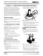
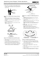
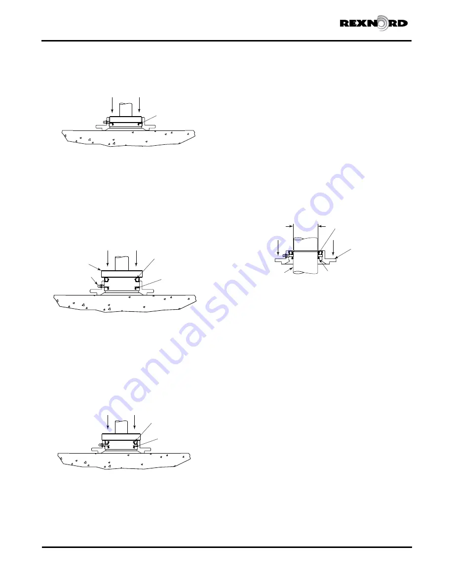
5. With an arbor press or a hydraulic press, carefully push
seal into seal carrier until the seal seats flush to the
shelf of the seal carrier (reference Figure 6.2.4.1B).
OUTBOARD SIDE
INBOARD SIDE
DOUBLE LIPED
INBOARD SEAL
(INSTALLED)
Figure 6.2.4.1B Installation of Inboard Seal
NOTE
: Be sure to push seal in squarely. Any
misalignment might damage seal and result in oil
leakage.
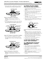
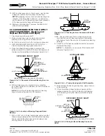
6. Set the single lipped seal on the seal carrier so that the
opening on the seal where the garter spring is located
faces the outboard side (reference Figure 6.2.4.2A).
OUTBOARD SIDE
INBOARD SIDE
GARTER SPRING ON
SINGLE LIPPED
OUTBOARD SEAL
DOUBLE LIPPED
INBOARD SEAL
(INSTALLED)
ARBOR PRESS
OR
HYDRAULIC PRESS
GREASE
FITTING
Figure 6.2.4.2A Placement of Outboard Seal for Installation
7. With an arbor press or a hydraulic press, carefully
push seal into seal carrier until the seal seats flush to
the outboard face of the seal carrier (reference Figure
6.2.4.2B).
INBOARD SIDE
OUTBOARD SIDE
SINGLE LIPPED
OUTBOARD SEAL
(INSTALLED)
DOUBLE LIPPED
INBOARD SEAL
(INSTALLED)
NOTE
: Be sure to push seal in squarely. Any
misalignment might damage seal and result in oil
leakage.
Figure 6.2.4.2B Installation of Outboard Seal
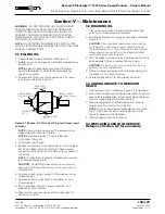
6.2.5 INSTALLING SEAL CARRIER -
INPUT/OUTPUT SHAFT ASSEMBLY
1. Clean the machined surfaces where the seal carrier
and the input or output housing mate.
NOTE
: Scraping of surfaces with a putty knife may be
required.
2. Apply a bead of sealant around the inboard lip of the
seal carrier and/ or around the face of the input or
output housing inside the bolt hole circle.
NOTE
: Use Loctite 515 gasket eliminator, or equivalent
as a sealant.
3. Slip the seal carrier over the shaft.
CAUTION
: Extreme care must be taken to not roll the lip
of the seal or cut the seal on the keyway.
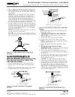
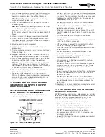
4. When the seal carrier is piloted on the shaft pilot, seat
the seal carrier by slowly pressing down on the flange;
reference Figure 6.2.5.
SEAL
DIAMETER
SHAFT
FLANGE
DOUBLE LIPPED
INBOARD SEAL
SINGLE LIPPED
OUTBOARD SEAL
Figure 6.2.5 Placement of Seal Carrier Assembly onto
Shaft
NOTE
: Orientate the seal carrier grease fitting to the
position best suited to your application. Reducers are
assembled at the Factory with the grease fitting oriented
in-line with an oil port in the input or output shaft
housings and are normally in the 12 o’clock position.
5. Bolt seal carrier to input or output housing, reference
Table 16 (Page 28) for bolt torques.
6. Add grease to seal carrier; reference Section 5.3.
7. Add oil to reducer; reference Section 5.1.
6.3 REPLACING BEARINGS - INPUT/
OUTPUT SHAFT ASSEMBLIES
6.3.1 REMOVING INPUT OR OUTPUT
SHAFT ASSEMBLIES TO REPLACE
BEARINGS
1. Take reducer out of service; reference Section 6.1.
2. Clean all external surfaces to prevent contaminants
from entering unit when disassembled.
3. Drain oil from unit; reference Section 5.2.
4. If unit is equipped with a fan and shroud, remove fan
and shroud.
NOTE
: For better results, mount reducer in the vertical
position; reference Steps A, B, and C.
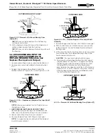
5. Remove the bolts that attach the assembly to the
maincase.
Summary of Contents for CD-1261
Page 1: ... 0 1 2121 3 4 1 5 6 ...
Page 2: ... ...
Page 3: ... ...
Page 4: ... ...
Page 5: ... ...
Page 6: ... 0 1 2 3 4 5 6 5 6 7 1 1 5 6 5 6 5 6 1 0 0 ...
Page 7: ... ...
Page 8: ... 0 1 2 0 3 0 ...
Page 9: ... ...
Page 10: ... 0 12 2 0 3 4 5 5 5 0 0 ...
Page 11: ... 6 12 0 0 7 5 5 0 8 0 8 5 0 50 9 4 12 0 0 9 4 0 9 64 0 5 0 0 1 0 0 ...
Page 12: ... 0 2 0 0 3 0 6 6 6 6 6 0 0 0 5 5 0 6 0 ...
Page 14: ... ...
Page 15: ... 0 0 1 1 2 1 1 3 0 4 5 1 0 1 0 0 2 1 2 1 0 0 0 2 1 1 1 1 1 0 0 0 1 0 0 0 1 0 1 6 1 1 ...
Page 17: ... 1 0 3 0 0 1 1 1 71 0 0 1 1 1 0 1 1 ...
Page 18: ... ...
Page 25: ... 8 ...
Page 28: ... 1 7 4 0 4 1 4 1 1 4 1 1 1 4 85 4 4 1 4 1 4 0 6 4 1 1 1 01 0 1 4 6 4 1 1 4 L 1 ...
Page 29: ... 4 ...
Page 30: ... 0 1 2 3 24 3 5 6 4 5 6 4 5 5 1 5 4 74 8 5 9 1 4 27 3 5 4 74 8 5 5 29 13 27 3 1 29 13 5 1 ...
Page 31: ... 8 8 80 1 2 3 5 6 4 5 6 4 5 5 1 5 A 9 1 B 4 27 3 888 7 8 0 B 4 C D 5 29 13 B 27 3 888 7 29 13 ...
Page 32: ... 4 24 3 5 6 4 5 6 4 5 5 4 7 M 7 4 7 N 2 0 7 2 M 0 N M ...
Page 35: ... 8 G 8 0 G 4 88 8E 1 2 3 5 6 4 5 6 4 5 5 1 4 1 4 27 3 1 088 7 5 4 1 5 29 13 H 27 3 088 7 ...
Page 36: ... E 5 ...
Page 37: ... 9 4 5 H 0 1 2034 2034 2034 2034 0 5 1 6 71 6 1 2 1 1 1 0 1 81 1 9 9 ...
Page 38: ... 1 5 1 5 1 3 05 3 1 0 1 1 6 A 6 1 A 6 B 1 6 B 6 1 1 1 6 6 6 2 9 0 6 ...
Page 39: ... 0 ...
Page 40: ... 0 0 ...
Page 42: ......
Page 43: ... 0122 3 4 5 6 4 4 4 4 5 4 4 4 4 4 7 7 4 4 6 4 4 5 5 4 5 8 8 3 5 3 5 3 5 3 5 5 ...
Page 44: ... 0 0 0 0 0 0 0 0 0 0 1 1 2 3 0 3 3 0 0 33 0 3 0 3 3 0 ...
Page 46: ... 011 2 3 3 4 3 2 5 5 6 ...
Page 47: ... 011 2 3 4 5 3 6 3 7 7 2 4 ...
Page 48: ... 00 1 2 3 4 3 5 5 5 5 5 3 1 1 2 2 6 1 1 1 5 5 7 5 5 5 5 ...
Page 49: ... 0122 3 4 5 6 7 4 8 4 4 8 4 4 8 5 5 5 5 5 5 5 5 5 5 5 5 ...
Page 50: ... 0 11 2 2 2 2 2 3 4 5 0 5 3 6 7 6 6 8 9 8 9 6 6 8 9 0 1 1 1 1 1 8 9 1 1 1 5 ...
Page 51: ... 011 2 3 4 5 4 2 2 2 6 2 6 6 3 3 3 3 3 3 3 ...
Page 53: ... 011 2 3 4 5 4 2 6 33 2 33 6 6 6 ...
Page 54: ... 011 2 3 3 3 3 4 5 4 33 2 33 6 3 3 3 ...
Page 56: ... 0122 3 4 5 6 7 8 4 4 5 8 4 4 8 9 9 9 8 4 4 4 88 8 8 8 ...
Page 57: ... 0 1 1 1 2 1 3 1 1 1 0 1 1 1 4 1 1 ...
Page 58: ... ...
Page 59: ... ...
Page 96: ...Bearing Maintenance Guide x Lubrication x Troubleshooting ...
Page 97: ......
Page 98: ......
Page 99: ......
Page 100: ......
Page 101: ......
Page 102: ......
Page 103: ......
Page 104: ......
Page 105: ......
Page 106: ......
Page 107: ......
Page 108: ......
Page 109: ......
Page 110: ......
Page 111: ......
Page 112: ......
Page 113: ......
Page 114: ......
Page 115: ......
Page 116: ......
Page 117: ......
Page 118: ......
Page 119: ......
Page 120: ......
Page 121: ......
Page 122: ......
Page 123: ......
Page 124: ......
Page 125: ......
Page 126: ......
Page 165: ... 0 0 1 2 3 4 5 6 52 3 52 3 7 8 4 6 52 4 6 1 9 9 9 9 9 ...
Page 166: ... 0 5 9 9 2 2 4 6 4 6 4 6 7 8 7 8 2 4 6 4 7 8 7 8 2 4 6 4 6 52 A ...
Page 167: ... 0 0 1 2 1 2 3 4 2 1 2 3 4 ...
Page 168: ... 0 2 1 2 3 3 4 2 1 2 3 4 2 ...
Page 194: ......
Page 195: ......
Page 196: ......
Page 218: ......
Page 219: ......
Page 234: ...15 Notes Model 121 Regulators Brochure ...
Page 236: ......

