Owners Manual
s
Rexnord
®
Planetgear™ 7000 Series Speed Reducers
(Page 20 of 32) Sizes Neptune, Neptune Plus, Orion Plus, Saturn Plus & Titan Plus
158-170
Rexnord
January 2015
3001 W. Canal St., Milwaukee, WI 53208-4200 USA
Supersedes 11-12
Telephone:414-342-3131 Fax: 414-937-4359 www.rexnord.com
NOTE
: Any gap between shaft and bearing cone can
result excessive axial bearing clearance or bearing
misalignment and ultimately result in premature bearing
damage.
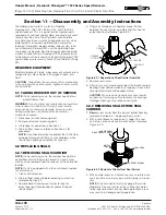
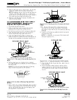
7. Carefully set the housing, outboard side face down,
onto the outboard bearings.
NOTE
: It is helpful to use a crane to lift hub onto shaft;
reference Figure 6.3.5.4.
8. While rotating the housing on bearings, apply clean oil
to the bearings.
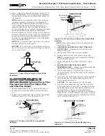
9. Place the inboard bearing cone squarely on the inboard
end of the shaft with the smaller diameter of the
bearing facing the outboard; reference Figure 6.3.5.5.
10. With an arbor press or a hydraulic press carefully push
bearing cone. When bearings begin to approach the
bearing cup, apply clean oil to inboard bearings.
INBOARD SIDE
INBOARD
BEARING CONE
OUTBOARD
BEARING CONE
Figure 6.3.5.5 — Placement of Inboard Bearing Cone on
Shaft
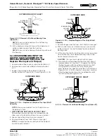
BACKSTOP
ASSEMBLY
BACKSTOP
PAWLS
CLOCKWISE ROTATION
OF OUTPUT SHAFT
COUNTER-CLOCKWISE ROTATION
OF OUTPUT SHAFT
Figure 6.3.5.6 Backstop on Input Assembly
NOTE
: DO NOT push on bearing rollers or bearing
cage; reference Figure 6.3.5.2.
11. Press inboard bearing until it touches the surface of
the bearing cup.
NOTE
: Do not over push bearings into cup. This might
cause the bearings to Brinell the cup.
NOTE
: An indication when the inboard bearing is fully
seated is when the hub will not rotate on the shaft
freely.
12.
INPUT ONLY
- Clean and place the backstop or
backstop spacer onto the shaft.
NOTE
: The desired rotation of the reducer is
determined by viewing thru the output shaft side.
Reference Figure 6.3.5.6 for orientation of the backstop
after being assembled onto the input shaft.
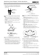
6. With a 0.001” or 0.040 mm mm feeler gage, make sure
that there is no gap between the shaft shoulder and the
bearing cone to insure proper cone seating; reference
Figure 6.3.5.3.
OUTBOARD
BEARING CONE
CHECK
THIS AREA
FOR GAP
Figure 6.3.5.3 Checking for Zero Clearance with Feeler
Gauge
OUTBOARD
BEARING CONE
SHAFT
PILOT
INBOARD SIDE
CHAIN
EYEBOLT
Figure 6.3.5.4—Placing Housing onto Shaft Assembly
13. Clean and place the tongued washer onto the shaft.
14. Clean clampnut. Place it with the grooved side down
(or groove towards bearings) and thread on clampnut
until it is unable to rotate.
15. Mark the location of the clampnut.
16. Loosen clampnut approximately
¾
” (19 mm) from
original mark.
17. Tighten socket head cap screw on clampnut; reference
Table 15, Page 23.
18. Support hub and affix to work table with the shaft not
touching the table; reference Figure 6.4.1. (Page 21).
Summary of Contents for CD-1261
Page 1: ... 0 1 2121 3 4 1 5 6 ...
Page 2: ... ...
Page 3: ... ...
Page 4: ... ...
Page 5: ... ...
Page 6: ... 0 1 2 3 4 5 6 5 6 7 1 1 5 6 5 6 5 6 1 0 0 ...
Page 7: ... ...
Page 8: ... 0 1 2 0 3 0 ...
Page 9: ... ...
Page 10: ... 0 12 2 0 3 4 5 5 5 0 0 ...
Page 11: ... 6 12 0 0 7 5 5 0 8 0 8 5 0 50 9 4 12 0 0 9 4 0 9 64 0 5 0 0 1 0 0 ...
Page 12: ... 0 2 0 0 3 0 6 6 6 6 6 0 0 0 5 5 0 6 0 ...
Page 14: ... ...
Page 15: ... 0 0 1 1 2 1 1 3 0 4 5 1 0 1 0 0 2 1 2 1 0 0 0 2 1 1 1 1 1 0 0 0 1 0 0 0 1 0 1 6 1 1 ...
Page 17: ... 1 0 3 0 0 1 1 1 71 0 0 1 1 1 0 1 1 ...
Page 18: ... ...
Page 25: ... 8 ...
Page 28: ... 1 7 4 0 4 1 4 1 1 4 1 1 1 4 85 4 4 1 4 1 4 0 6 4 1 1 1 01 0 1 4 6 4 1 1 4 L 1 ...
Page 29: ... 4 ...
Page 30: ... 0 1 2 3 24 3 5 6 4 5 6 4 5 5 1 5 4 74 8 5 9 1 4 27 3 5 4 74 8 5 5 29 13 27 3 1 29 13 5 1 ...
Page 31: ... 8 8 80 1 2 3 5 6 4 5 6 4 5 5 1 5 A 9 1 B 4 27 3 888 7 8 0 B 4 C D 5 29 13 B 27 3 888 7 29 13 ...
Page 32: ... 4 24 3 5 6 4 5 6 4 5 5 4 7 M 7 4 7 N 2 0 7 2 M 0 N M ...
Page 35: ... 8 G 8 0 G 4 88 8E 1 2 3 5 6 4 5 6 4 5 5 1 4 1 4 27 3 1 088 7 5 4 1 5 29 13 H 27 3 088 7 ...
Page 36: ... E 5 ...
Page 37: ... 9 4 5 H 0 1 2034 2034 2034 2034 0 5 1 6 71 6 1 2 1 1 1 0 1 81 1 9 9 ...
Page 38: ... 1 5 1 5 1 3 05 3 1 0 1 1 6 A 6 1 A 6 B 1 6 B 6 1 1 1 6 6 6 2 9 0 6 ...
Page 39: ... 0 ...
Page 40: ... 0 0 ...
Page 42: ......
Page 43: ... 0122 3 4 5 6 4 4 4 4 5 4 4 4 4 4 7 7 4 4 6 4 4 5 5 4 5 8 8 3 5 3 5 3 5 3 5 5 ...
Page 44: ... 0 0 0 0 0 0 0 0 0 0 1 1 2 3 0 3 3 0 0 33 0 3 0 3 3 0 ...
Page 46: ... 011 2 3 3 4 3 2 5 5 6 ...
Page 47: ... 011 2 3 4 5 3 6 3 7 7 2 4 ...
Page 48: ... 00 1 2 3 4 3 5 5 5 5 5 3 1 1 2 2 6 1 1 1 5 5 7 5 5 5 5 ...
Page 49: ... 0122 3 4 5 6 7 4 8 4 4 8 4 4 8 5 5 5 5 5 5 5 5 5 5 5 5 ...
Page 50: ... 0 11 2 2 2 2 2 3 4 5 0 5 3 6 7 6 6 8 9 8 9 6 6 8 9 0 1 1 1 1 1 8 9 1 1 1 5 ...
Page 51: ... 011 2 3 4 5 4 2 2 2 6 2 6 6 3 3 3 3 3 3 3 ...
Page 53: ... 011 2 3 4 5 4 2 6 33 2 33 6 6 6 ...
Page 54: ... 011 2 3 3 3 3 4 5 4 33 2 33 6 3 3 3 ...
Page 56: ... 0122 3 4 5 6 7 8 4 4 5 8 4 4 8 9 9 9 8 4 4 4 88 8 8 8 ...
Page 57: ... 0 1 1 1 2 1 3 1 1 1 0 1 1 1 4 1 1 ...
Page 58: ... ...
Page 59: ... ...
Page 96: ...Bearing Maintenance Guide x Lubrication x Troubleshooting ...
Page 97: ......
Page 98: ......
Page 99: ......
Page 100: ......
Page 101: ......
Page 102: ......
Page 103: ......
Page 104: ......
Page 105: ......
Page 106: ......
Page 107: ......
Page 108: ......
Page 109: ......
Page 110: ......
Page 111: ......
Page 112: ......
Page 113: ......
Page 114: ......
Page 115: ......
Page 116: ......
Page 117: ......
Page 118: ......
Page 119: ......
Page 120: ......
Page 121: ......
Page 122: ......
Page 123: ......
Page 124: ......
Page 125: ......
Page 126: ......
Page 165: ... 0 0 1 2 3 4 5 6 52 3 52 3 7 8 4 6 52 4 6 1 9 9 9 9 9 ...
Page 166: ... 0 5 9 9 2 2 4 6 4 6 4 6 7 8 7 8 2 4 6 4 7 8 7 8 2 4 6 4 6 52 A ...
Page 167: ... 0 0 1 2 1 2 3 4 2 1 2 3 4 ...
Page 168: ... 0 2 1 2 3 3 4 2 1 2 3 4 2 ...
Page 194: ......
Page 195: ......
Page 196: ......
Page 218: ......
Page 219: ......
Page 234: ...15 Notes Model 121 Regulators Brochure ...
Page 236: ......

