Rexnord
®
Planetgear™ 7000 Series Speed Reducer
s
Owners Manual
Sizes Neptune, Neptune Plus, Orion Plus, Saturn Plus & Titan Plus (Page 23 of 32)
Rexnord
158-170
3001 W. Canal St., Milwaukee, WI 53208-4200
January 2015
Telephone: 414-937-4359 Fax: 414-937-4359 www.rexnord.com
Supersedes 11-12
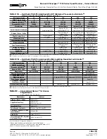
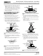
TABLE 15 — Socket Head Cap Screw Torque
DRIVE
SERIES
Cap Screw Torque (ft-lb)
Inupt
Output
Neptune
15
54
Neptune Plus
15
54
Orion Plus
15
54
Saturn Plus
14
54
Titan Plus
14
54
SINGLE REDUCTION
c
d
e
f
g
h
DOUBLE REDUCTION
c
d e f
g
h
i
j
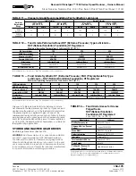
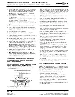
6.4.3 ADJUSTING FOR TOO LITTLE AXIAL
BEARING CLEARANCE
1. Loosen socket head cap screw on clampnut.
2. Mark the position of the clampnut.
3. Rotate clampnut 1/16” to 1/8” (1.5 to 3.1 mm) in the
counter clockwise direction from mark to loosen
clampnut.
NOTE
: The measurement given is an estimate.
4. With an arbor press or hydraulic press, push on the
clampnut end of shaft to increase the bearing axial
clearance.
5. Follow procedures in Section 6.4.1 to determine new
axial bearing clearance.
6. Repeat first 5 steps if axial bearing clearance is found
to be still too little.
6.4.4 FINAL TIGHTENING OF LOCK
SCREW ON CLAMPNUT
1. Tighten torque socket head cap screw on clampnut to
value below.
TRIPLE REDUCTION
c d e
f g h
i
j
k
l
QUADRUPLE REDUCTION
c d e f g h i jkl
11
O
13
O
O
12
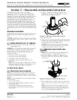
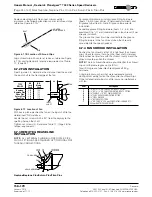
6.5 GEAR TRAIN DISASSEMBLY
Place gears in a clean dry place in the order of
disassembly. Exploded view drawings of a specific gear
train may be requested from the factory by specifying
the reducer serial number, model number, size, ratio, and
rating. To order replacement components, please give the
previously stated information about the reducer and the
items needed. Reference the following sketches for general
exploded view drawings.
NOTE
: All the gearing is stabilized at the output assembly.
Removing output assembly first may result in a difficult time
reassembling reducer. It is recommended that the input
assembly be removed first, then the gear train, and finally
the output assembly.
Single Reduction Disassembly
— Remove input assembly
(1) from maincase (5). Remove input gear (2), ring gear
(4), and last stage carrier (3). Remove output assembly (6)
from maincase.
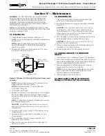
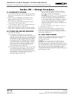
CLIP LOCATIONS
12 O’CLOCK
POSITION
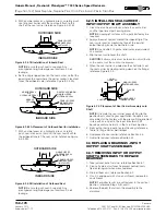
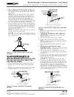
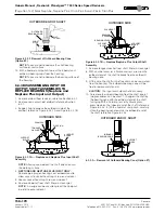
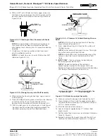
Figure 6.7.1A Location of Shroud Clips
Double Reduction Disassembly
— Rem;ove input
assembly (1) from maincase (7). Remove input gear (2),
ring gear (6), first stage carrier (3), last stage sun gear
(4), and last stage carrier (5). Remove output assembly (8)
from maincase.
Triple Reduction Disassembly
— Remove input assembly
(1) from maincase (9). Remove input gear (2), first stage
carrier (3), ring gear (8), second stage sun gear (4),
second stage carrier (5), last stage sun gear (6), and
last stage carrier (7). Remove output assembly (10) from
maincase.
Quadruple Reduction disassembly
— Remove input
assembly (1) from maincase (12). Remove input gear
(2), first stage carrier (3), ring gear adapter (4), second
stage sun gear (5), second stage carrier (6), ring gear (1),
third stage sun gear (7), third stage carrier (8), last stage
sun gear (9), and last stage carrier (10). Remove output
assembly (13) from maincase.
6.6 GEAR TRAIN ASSEMBLY
The gear train can be assembled in the reverse order of
disassembly. Reference Section 6.5.
NOTE
: It is recommended that the output sub-assembly be
installed first, then the gear train, and finally the input sub-
assemble. Unit should be assemble in the vertical position,
with input shaft up.
6.7 FAN AND SHROUD INSTALLATION
6.7.1 SHROUD CLIP INSTALLATION
Summary of Contents for CD-1261
Page 1: ... 0 1 2121 3 4 1 5 6 ...
Page 2: ... ...
Page 3: ... ...
Page 4: ... ...
Page 5: ... ...
Page 6: ... 0 1 2 3 4 5 6 5 6 7 1 1 5 6 5 6 5 6 1 0 0 ...
Page 7: ... ...
Page 8: ... 0 1 2 0 3 0 ...
Page 9: ... ...
Page 10: ... 0 12 2 0 3 4 5 5 5 0 0 ...
Page 11: ... 6 12 0 0 7 5 5 0 8 0 8 5 0 50 9 4 12 0 0 9 4 0 9 64 0 5 0 0 1 0 0 ...
Page 12: ... 0 2 0 0 3 0 6 6 6 6 6 0 0 0 5 5 0 6 0 ...
Page 14: ... ...
Page 15: ... 0 0 1 1 2 1 1 3 0 4 5 1 0 1 0 0 2 1 2 1 0 0 0 2 1 1 1 1 1 0 0 0 1 0 0 0 1 0 1 6 1 1 ...
Page 17: ... 1 0 3 0 0 1 1 1 71 0 0 1 1 1 0 1 1 ...
Page 18: ... ...
Page 25: ... 8 ...
Page 28: ... 1 7 4 0 4 1 4 1 1 4 1 1 1 4 85 4 4 1 4 1 4 0 6 4 1 1 1 01 0 1 4 6 4 1 1 4 L 1 ...
Page 29: ... 4 ...
Page 30: ... 0 1 2 3 24 3 5 6 4 5 6 4 5 5 1 5 4 74 8 5 9 1 4 27 3 5 4 74 8 5 5 29 13 27 3 1 29 13 5 1 ...
Page 31: ... 8 8 80 1 2 3 5 6 4 5 6 4 5 5 1 5 A 9 1 B 4 27 3 888 7 8 0 B 4 C D 5 29 13 B 27 3 888 7 29 13 ...
Page 32: ... 4 24 3 5 6 4 5 6 4 5 5 4 7 M 7 4 7 N 2 0 7 2 M 0 N M ...
Page 35: ... 8 G 8 0 G 4 88 8E 1 2 3 5 6 4 5 6 4 5 5 1 4 1 4 27 3 1 088 7 5 4 1 5 29 13 H 27 3 088 7 ...
Page 36: ... E 5 ...
Page 37: ... 9 4 5 H 0 1 2034 2034 2034 2034 0 5 1 6 71 6 1 2 1 1 1 0 1 81 1 9 9 ...
Page 38: ... 1 5 1 5 1 3 05 3 1 0 1 1 6 A 6 1 A 6 B 1 6 B 6 1 1 1 6 6 6 2 9 0 6 ...
Page 39: ... 0 ...
Page 40: ... 0 0 ...
Page 42: ......
Page 43: ... 0122 3 4 5 6 4 4 4 4 5 4 4 4 4 4 7 7 4 4 6 4 4 5 5 4 5 8 8 3 5 3 5 3 5 3 5 5 ...
Page 44: ... 0 0 0 0 0 0 0 0 0 0 1 1 2 3 0 3 3 0 0 33 0 3 0 3 3 0 ...
Page 46: ... 011 2 3 3 4 3 2 5 5 6 ...
Page 47: ... 011 2 3 4 5 3 6 3 7 7 2 4 ...
Page 48: ... 00 1 2 3 4 3 5 5 5 5 5 3 1 1 2 2 6 1 1 1 5 5 7 5 5 5 5 ...
Page 49: ... 0122 3 4 5 6 7 4 8 4 4 8 4 4 8 5 5 5 5 5 5 5 5 5 5 5 5 ...
Page 50: ... 0 11 2 2 2 2 2 3 4 5 0 5 3 6 7 6 6 8 9 8 9 6 6 8 9 0 1 1 1 1 1 8 9 1 1 1 5 ...
Page 51: ... 011 2 3 4 5 4 2 2 2 6 2 6 6 3 3 3 3 3 3 3 ...
Page 53: ... 011 2 3 4 5 4 2 6 33 2 33 6 6 6 ...
Page 54: ... 011 2 3 3 3 3 4 5 4 33 2 33 6 3 3 3 ...
Page 56: ... 0122 3 4 5 6 7 8 4 4 5 8 4 4 8 9 9 9 8 4 4 4 88 8 8 8 ...
Page 57: ... 0 1 1 1 2 1 3 1 1 1 0 1 1 1 4 1 1 ...
Page 58: ... ...
Page 59: ... ...
Page 96: ...Bearing Maintenance Guide x Lubrication x Troubleshooting ...
Page 97: ......
Page 98: ......
Page 99: ......
Page 100: ......
Page 101: ......
Page 102: ......
Page 103: ......
Page 104: ......
Page 105: ......
Page 106: ......
Page 107: ......
Page 108: ......
Page 109: ......
Page 110: ......
Page 111: ......
Page 112: ......
Page 113: ......
Page 114: ......
Page 115: ......
Page 116: ......
Page 117: ......
Page 118: ......
Page 119: ......
Page 120: ......
Page 121: ......
Page 122: ......
Page 123: ......
Page 124: ......
Page 125: ......
Page 126: ......
Page 165: ... 0 0 1 2 3 4 5 6 52 3 52 3 7 8 4 6 52 4 6 1 9 9 9 9 9 ...
Page 166: ... 0 5 9 9 2 2 4 6 4 6 4 6 7 8 7 8 2 4 6 4 7 8 7 8 2 4 6 4 6 52 A ...
Page 167: ... 0 0 1 2 1 2 3 4 2 1 2 3 4 ...
Page 168: ... 0 2 1 2 3 3 4 2 1 2 3 4 2 ...
Page 194: ......
Page 195: ......
Page 196: ......
Page 218: ......
Page 219: ......
Page 234: ...15 Notes Model 121 Regulators Brochure ...
Page 236: ......

