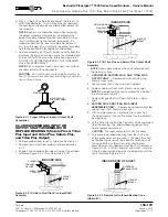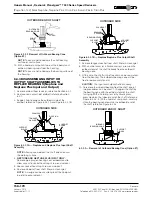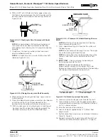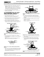
Rexnord
®
Planetgear™ 7000 Series Speed Reducer
s
Owners Manual
Sizes Neptune, Neptune Plus, Orion Plus, Saturn Plus & Titan Plus (Page 25 of 32)
Rexnord
158-170
3001 W. Canal St., Milwaukee, WI 53208-4200
January 2015
Telephone: 414-937-4359 Fax: 414-937-4359 www.rexnord.com
Supersedes 11-12
Section VII — Vertical Service
l
INPUT SHAFT UP ORIENTATION
FINAL
BEARING DRAIN
MAIN OIL CRAIN
IN MAINCASE
PRIMARY
OIL FILL
SECONDARY
OIL FILL
c
d
e
f
g
h
i
j
k
11
14
12
13
12
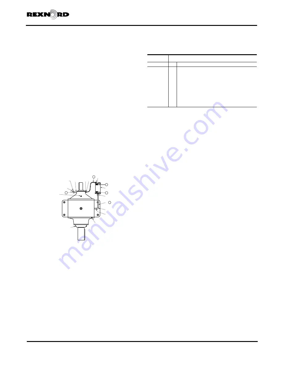
Figure 7.1a Vertical Service Shaft Orientations
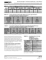
TABLE 7.1b — Vertical Service (Standard
Reducers)
Neptune/
Neptune Plus
Quantity
Item
Description
1
14
1/2” NPT x 10” LG. PIPE NIPPLE (250 mm)
1
13
3/8” NPT x 90° PIPE ELBOW
2
12
OIL LEVEL DECAL
1
11
1/4” O.D. PLASTIC TUBE X 24” LG. (600 mm)
1
10
3/8” NPT x 1/8” HEX REDUCING BUSHING
1
9
1/8” NPT x 1/4” O.D. TUBE STRAIGHT BRASS FITTING
1
8
1/8” NPT x 1/4” O.D. TUBE 90° BRASS FITTING
1
7
1/2” NPT PIPE COUPLING
. . .
6
1/2” NPT x 12” LG. PIPE NIPPLE (300 mm)
1
5
3/8” SQ. HD. PIPE PLUG
1
4
1/2” NPT x 3” LG. PIPE NIPPLE (75 mm)
1
3
1/2” NPT X 90° PIPE ELBOW
1
2
3/8” NPT x 3” LG. PIPE NIPPLE (75 mm)
1
1
RESERVOIR 1/2 GALLON (1.89L)
NOTE
: All external plumbing (pipe nipple, pipe
plugs, fittings) are standard npt (national pipe thread)
connections.
Vertical service can be either input, or output shaft
up. Standard reducers are not designed for vertical
applications. Modifications are made at the factory to
convert a standard reducer for vertical service.
Planetgear speed reducers used in a vertical orientation
or most inclined orientations require an oil reservoir
lubrication system. Any mounting orientation other than
horizontal must be stated at order placement so Rexnord
can determine the requirement for a reservoir kit.
The reservoir kit works by providing an adequate head of
oil to lubricate the uppermost bearing while allowing for oil
expansion. A plastic tube acts as a purge line to eliminate
trapped air below the seals.
CAUTION
: Failure to use a properly installed reservoir kit
will cause premature speed reducer damage.
Assemble components as shown in Figure 7.1a and Table
7.1b. It is difficult to determine all potential field installation
interference points. If necessary please substitute different
pipe fittings as required. In doing so, it is important that
the bottom of the reservoir is at or above the uppermost
bearing. Holes have been drilled by the factory to facilitate
both right hand or left hand oil reservoir mounting. Apply
pipe sealant to all threaded connections during assembly.
FILLING OIL
The speed reducer should be completely filled with oil
prior to start-up. Refer to the Lubrication section for correct
oil type and viscosity.
NOTE
: When replacing oil plug, seal it in the process using
thread sealant.
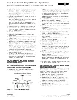
1. Begin by filling the reducer thru the primary oil fill in the
maincase until full. Reference Figure 7.1a.
2. Plug primary oil fill and fill thru secondary oil fill until full.
3. Plug secondary oil fill and fill reservoir until proper oil
level is reached.
4. Start reducer under a no-load condition.
NOTE
: During start-up and initially after, it is important
to monitor the oil level, as any remaining trapped
air may need to purge out. Add oil as needed if this
occurs.
DRAINING OIL
CAUTION
: Oil may be hot. Do not drain oil until oil is at
ambient or a safe temperature.
NOTE
: When replacing oil plug, seal it in the process using
thread sealant.
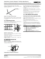
1. Begin by draining oil from main oil drain in maincase.
Reference Figure 7.1a.
2. Plug main oil drain and begin draining oil from final
bearing drain.
Summary of Contents for CD-1261
Page 1: ... 0 1 2121 3 4 1 5 6 ...
Page 2: ... ...
Page 3: ... ...
Page 4: ... ...
Page 5: ... ...
Page 6: ... 0 1 2 3 4 5 6 5 6 7 1 1 5 6 5 6 5 6 1 0 0 ...
Page 7: ... ...
Page 8: ... 0 1 2 0 3 0 ...
Page 9: ... ...
Page 10: ... 0 12 2 0 3 4 5 5 5 0 0 ...
Page 11: ... 6 12 0 0 7 5 5 0 8 0 8 5 0 50 9 4 12 0 0 9 4 0 9 64 0 5 0 0 1 0 0 ...
Page 12: ... 0 2 0 0 3 0 6 6 6 6 6 0 0 0 5 5 0 6 0 ...
Page 14: ... ...
Page 15: ... 0 0 1 1 2 1 1 3 0 4 5 1 0 1 0 0 2 1 2 1 0 0 0 2 1 1 1 1 1 0 0 0 1 0 0 0 1 0 1 6 1 1 ...
Page 17: ... 1 0 3 0 0 1 1 1 71 0 0 1 1 1 0 1 1 ...
Page 18: ... ...
Page 25: ... 8 ...
Page 28: ... 1 7 4 0 4 1 4 1 1 4 1 1 1 4 85 4 4 1 4 1 4 0 6 4 1 1 1 01 0 1 4 6 4 1 1 4 L 1 ...
Page 29: ... 4 ...
Page 30: ... 0 1 2 3 24 3 5 6 4 5 6 4 5 5 1 5 4 74 8 5 9 1 4 27 3 5 4 74 8 5 5 29 13 27 3 1 29 13 5 1 ...
Page 31: ... 8 8 80 1 2 3 5 6 4 5 6 4 5 5 1 5 A 9 1 B 4 27 3 888 7 8 0 B 4 C D 5 29 13 B 27 3 888 7 29 13 ...
Page 32: ... 4 24 3 5 6 4 5 6 4 5 5 4 7 M 7 4 7 N 2 0 7 2 M 0 N M ...
Page 35: ... 8 G 8 0 G 4 88 8E 1 2 3 5 6 4 5 6 4 5 5 1 4 1 4 27 3 1 088 7 5 4 1 5 29 13 H 27 3 088 7 ...
Page 36: ... E 5 ...
Page 37: ... 9 4 5 H 0 1 2034 2034 2034 2034 0 5 1 6 71 6 1 2 1 1 1 0 1 81 1 9 9 ...
Page 38: ... 1 5 1 5 1 3 05 3 1 0 1 1 6 A 6 1 A 6 B 1 6 B 6 1 1 1 6 6 6 2 9 0 6 ...
Page 39: ... 0 ...
Page 40: ... 0 0 ...
Page 42: ......
Page 43: ... 0122 3 4 5 6 4 4 4 4 5 4 4 4 4 4 7 7 4 4 6 4 4 5 5 4 5 8 8 3 5 3 5 3 5 3 5 5 ...
Page 44: ... 0 0 0 0 0 0 0 0 0 0 1 1 2 3 0 3 3 0 0 33 0 3 0 3 3 0 ...
Page 46: ... 011 2 3 3 4 3 2 5 5 6 ...
Page 47: ... 011 2 3 4 5 3 6 3 7 7 2 4 ...
Page 48: ... 00 1 2 3 4 3 5 5 5 5 5 3 1 1 2 2 6 1 1 1 5 5 7 5 5 5 5 ...
Page 49: ... 0122 3 4 5 6 7 4 8 4 4 8 4 4 8 5 5 5 5 5 5 5 5 5 5 5 5 ...
Page 50: ... 0 11 2 2 2 2 2 3 4 5 0 5 3 6 7 6 6 8 9 8 9 6 6 8 9 0 1 1 1 1 1 8 9 1 1 1 5 ...
Page 51: ... 011 2 3 4 5 4 2 2 2 6 2 6 6 3 3 3 3 3 3 3 ...
Page 53: ... 011 2 3 4 5 4 2 6 33 2 33 6 6 6 ...
Page 54: ... 011 2 3 3 3 3 4 5 4 33 2 33 6 3 3 3 ...
Page 56: ... 0122 3 4 5 6 7 8 4 4 5 8 4 4 8 9 9 9 8 4 4 4 88 8 8 8 ...
Page 57: ... 0 1 1 1 2 1 3 1 1 1 0 1 1 1 4 1 1 ...
Page 58: ... ...
Page 59: ... ...
Page 96: ...Bearing Maintenance Guide x Lubrication x Troubleshooting ...
Page 97: ......
Page 98: ......
Page 99: ......
Page 100: ......
Page 101: ......
Page 102: ......
Page 103: ......
Page 104: ......
Page 105: ......
Page 106: ......
Page 107: ......
Page 108: ......
Page 109: ......
Page 110: ......
Page 111: ......
Page 112: ......
Page 113: ......
Page 114: ......
Page 115: ......
Page 116: ......
Page 117: ......
Page 118: ......
Page 119: ......
Page 120: ......
Page 121: ......
Page 122: ......
Page 123: ......
Page 124: ......
Page 125: ......
Page 126: ......
Page 165: ... 0 0 1 2 3 4 5 6 52 3 52 3 7 8 4 6 52 4 6 1 9 9 9 9 9 ...
Page 166: ... 0 5 9 9 2 2 4 6 4 6 4 6 7 8 7 8 2 4 6 4 7 8 7 8 2 4 6 4 6 52 A ...
Page 167: ... 0 0 1 2 1 2 3 4 2 1 2 3 4 ...
Page 168: ... 0 2 1 2 3 3 4 2 1 2 3 4 2 ...
Page 194: ......
Page 195: ......
Page 196: ......
Page 218: ......
Page 219: ......
Page 234: ...15 Notes Model 121 Regulators Brochure ...
Page 236: ......

