background image

WIRING REQUIREMENTS

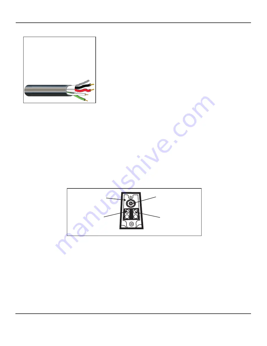
4 Conductor consisting of:

+

2 Conductor 

shielded

, 20  gauge 

with 22 gauge drain (microphone 
connection)

+

2 Conductor 

unshielded

, 18 gauge 

(speaker connection)

All in the same jacket

West Penn 356 or equivalent

SPEAKER CONNECTION OF TLO 

MICROPHONE CONNECTION OF TLO

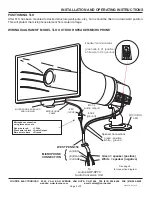
Speaker connection is located near the rear of the TLO and has a plexiglass window.  Remove window and 
connect the speaker portion of West Penn 356 (

green

 and 

white

 wires) to the two terminal screws marked 1 

and 2.

Green

 speaker wire goes to position 1 (positive)

White

 speaker wire goes to position 2 (negative)

The short cable extending from the back of the TLO is the microphone connection and consists of three wires:  

red,


black

 and 

bare

.  Using recommended wiring (West Penn 356 or equivalent), make microphone 

connections using 20 gauge wire nuts and matching 

red 

wire with 

red

black 

with 

black 

and 

bare 

wire with 

bare 

wire.  See diagram next page

.


see diagram below

Color code may vary if using wiring from other manufacturers

POWER TAP SETTINGS OF TLO

Located above the speaker connection of TLO is a set screw with a dial numbered 1 through 7.  Using a small 
screw driver, adjust the set screw to correspond to the proper power tap as shown below.

I

  Louroe Model TLO connected to Louroe AOP-SP70 

   conversion unit for interfacing with a DVR or IP Network Camera, use:

#2

  3.8W

Setting

Wattage

1

2

1

2

3

5

6

7

Speaker connection

(WHITE-negative)

Speaker connection

(GREEN-positive)

1 through 7

power tap settings

set screw

WIRING CONNECTIONS TO MODEL TLO 

COLOR CODE FOR RECOMMENDED CABLE

Red - 12Vdc Power
Black - Audio Output
Bare - Ground

Green - Speaker Positive
White - Speaker Ground

}

}

Microphone Portion

Speaker Portion

INSTALLATION AND OPERATING INSTRUCTIONS

Page 2 of 8

LOUROE  ELECTRONICS®    6 9 5 5   VA L J E A N   AVENUE,  VAN  NUYS,  CA  91406

TEL  (818)  994-6498

FAX 

994-6458

website: www.louroe.com                          e-mail: sales@louroe.com


(818)

aopsp70_ inst_3/15

Summary of Contents for AOP-SP70

Page 1: ... way speaker and microphone and re entry horn for high volume penetration Weatherized for outdoor applications the microphone and speaker horn are all within one housing In operation the TLO together with the AOP SP70 provides hands free bi directional audio communication with the audio receiving device DVR IP Camera etc MODEL AOP SP70 Speakerphone Conversion Unit MODEL TLO Outdoor Speaker Microph...

Page 2: ...red black with black and bare wire with bare wire See diagram next page see diagram below Color code may vary if using wiring from other manufacturers POWER TAP SETTINGS OF TLO Located above the speaker connection of TLO is a set screw with a dial numbered 1 through 7 Using a small screw driver adjust the set screw to correspond to the proper power tap as shown below I Louroe Model TLO connected t...

Page 3: ... using three wire nuts Red wire to red 12Vdc Black wire to black Audio Output Bare wire to bare Ground C BARE A RED B BLACK To Louroe AOP SP70 Audio Conversion Unit Green speaker positive White speaker negative Speaker terminal screws green wire to 1 positive white wire to 2 ground Speaker Connections green positive white ground 1 2 MICROPHONE CABLE MICROPHONE PC BOARD AND HOUSING INSTALLATION AND...

Page 4: ...ire goes to Pin SP Speaker Output NOTE Pin A is not used Both black and bare wire connect to Pin C CONNECTION FROM AOP SP70 TO DVR IP NETWORK CAMERA ETC After wiring connection has been applied to the 4 pin terminal block of the AOP SP70 run other end of cable to the audio receiving device s audio Input Output usually either RCA 3 5mm mono or 3 5mm stereo If Audio In Out of DVR IP Camera etc is 3 ...

Page 5: ...ded 18 gauge 20 gauge drain wire West Penn 356 or equivalent WIRING REQUIREMENTS FOR TLO MICROPHONE CABLE Microphone connection using three wire nuts Red 12Vdc Black Audio Output Bare Ground RED BLACK BARE WHITE SPEAKER GROUND GREEN SPEAKER POSITIVE Audio Out Audio Out Audio In Audio In Bare Wire Red Wire RCA CONNECTION 3 5mm MONO CONNECTION 3 5mm STEREO CONNECTION White Wire Black Wire Black Wire...

Page 6: ...L x 7 3 8 W x 2 3 4 H 3 lbs 8 5 oz 6 lbs 600 600 SPECIFICATIONS SPEAKER Power rating 30W max 167W setting 5 Dimensions Frequency response 11 W x 6 5 8 H x 12 3 4 D 350Hz to 14 kHz Input Weight of TLO 70V constant Voice coil impedance 8W 5 Lbs 5 oz INSTALLATION AND OPERATING INSTRUCTIONS Page 6 of 8 LOUROE ELECTRONICS 6 9 5 5 VA L J E A N AVENUE VAN NUYS CA 91406 TEL 818 994 6498 FAX 994 6458 websi...

Page 7: ...ATION AND OPERATING INSTRUCTIONS Page 7 of 8 LOUROE ELECTRONICS 6 9 5 5 VA L J E A N AVENUE VAN NUYS CA 91406 TEL 818 994 6498 FAX 994 6458 website www louroe com e mail sales louroe com 818 aopsp70_ inst_3 15 ...

Page 8: ...m a decal stating AUDIO MONITORING ON THESE PREMISES provided by Louroe Electronics must be installed in a visible location at the entrances and exits of both private and public buildings and vehicles This is to comply with United States Code Title 18 Section 2510 2 regarding rights of privacy it states Oral communication means any oral communication uttered by a person exhibiting an expectation t...

Reviews: