MHIT200D0207.doc 17/10/2011 Page 2/6
Impostazioni
•
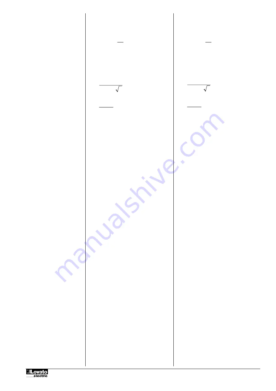
Manopole [1] e [3] – Impostazione del C/K del
relativo step. Il C/K viene calcolato con le
seguenti formule:
K
I
KStep
C
C
=
/
Dove:
K
= rapporto primario/secondario del TA utilizzato.
Ic
= Corrente nominale del banco di condensatori.
Nel caso la corrente nominale del condensatore non
sia disponibile, essa può essere calcolata con:
3
∗
=
cond
reattiva
V
P
Ic
(per sistemi trifase)
Oppure:
cond
reattiva
V
P
Ic
=
(per sistemi monofase)
•
Con Manopole [1] o [3] in posizione OFF il
relativo step è disabilitato.
•
Manopola [2] – Impostazione del ritardo di
inserimento.
•
Manopola [4] – Impostazione del ritardo di
disinserimento.
•
Selettore [5] – selezione della modalità di
collegamento monofase o trifase.
ATTENZIONE
Si consiglia di effettuare la scelta del modo di
funzionamento con apparecchio disalimentato allo
scopo di evitare situazioni anomale nel momento
del cambio funzione. E’ comunque possibile
effettuare il cambio con apparecchio alimentato.
1Ph
Inserzione in monofase. La misura della tensione
viene eseguita su L e N e la corrente viene
prelevata sulla fase L. Misurazione diretta
dell’angolo di sfasamento.
3Ph
Inserzione trifase. La misura della tensione viene
eseguita su L1, L2 e la corrente viene prelevata
da L3. Angolo di sfasamento con offset di 90°.
Nota:
Per il collegamento trifase, il segnale di corrente
DEVE essere prelevato dalla fase NON utilizzata
per il segnale di tensione. In caso contrario la
misura dell’angolo risulterà errata e di
conseguenza il funzionamento dell’apparecchio
risulterà compromesso.
Collegamento
Connettere il circuito di misura della corrente fra il
morsetto S1 e S2.
L’ingresso di corrente deve essere connesso
mediante TA esterno.
L’alimentazione ausiliaria dell’apparecchio
avviene tramite i morsetti A1 e A2.
Normale funzionamento
•
L’apparecchio misura la corrente reattiva
induttiva richiesta dal carico. Quando questa
supera quella di uno degli step disponibili, e la
situazione permane per un tempo superiore al
tempo di inserzione impostato, il gradino viene
inserito.
•
In caso la corrente reattiva risulti capacitiva,
quando questa supera il 75% del peso di uno
step attivato, e la situazione permane per il
tempo di disconnessione impostato, lo step
viene sganciato.
•
In sostanza l’apparecchio lavora per ridurre al
minimo possibile la corrente reattiva (tende a
Settings
•
Knobs [1] and [3] – Setting of C/K ratio of the
relevant step. The C/K ratio is calculated as
follows:
K
I
KStep
C
C
=
/
Where:
K
= Ratio between primary and secondary of the CT.
Ic
= Nominal current of capacitor bank.
Nel caso la corrente nominale del condensatore non
sia disponibile, essa può essere calcolata con:
3
∗
=
cond
reattiva
V
P
Ic
(per sistemi trifase)
Oppure:
cond
reattiva
V
P
Ic
=
(per sistemi monofase)
•
With knobs [1] or [3] in OFF position the
relevant step is disabled.
•
Knob [2] – Setting of the step connection delay
•
Knob [4] – Setting of the step disconnection
delay.
•
Selector [5] – Selection of wiring mode : Single-
phase or three-phase.
ATTENTION
It is recommended to make the operating mode
choice when the device is switched off to avoid
abnormal operation during function change.
It is however possible to make the change with a
powered device.
1Ph
Single-phase connection. Voltage measurement is
conducted on L and N; the current is
drawn on phase L.
The phase angle is measured without offset.
3Ph
Three-phase connection. The voltage
measurement is monitored on L1 and L2 ; the
current is drawn on phase L3. The current phase
angle has an offset of 90°.
Note
:
For three-phase connection, the current signal
MUST be taken from the phase that is NOT used
for voltage signal. Not respecting this rule will lead
to wrong angle measurement and consequent
wrong operation of the device.
Wiring
Connect the current measurement circuit between
terminals S1 and S2.
The current input must be connected by means of
external CT.
The auxiliary supply of the device is to be
connected at terminals A1 and A2.
Normal operation
•
The device measures the inductive reactive
current requested by the load. When it
overcomes the current set for one of the
available steps, and the situation lasts for more
than the set connection delay, the step is
connected.
•
In case the reactive current is capacitive, when
it is more than 75% of the current of an active
step, and this condition remains true for more
than the set disconnection delay, then the step
is disconnected.
•
In other words, the device works in order to
reduce the reactive current to the lowest


