I271
I
GB
F
E
02
17
31100324
G
B
6
MAIN MENU
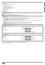
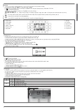
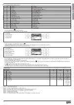
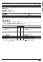
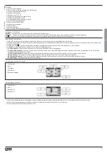
– The main menu is made up of a group of graphic icons (shortcuts) that allow rapid access to measurements and settings.
– Starting from normal viewing, press
MENU
key. The main menu screen is displayed.
– Press
to select the required function. The selected icon is highlighted and the central part of the display shows the description of the function.
– Press
to activate the selected function.
– If some functions are not available, the relevant icon will be disabled, that is shown in light grey.
–
etc. - Shortcuts that allow to jump to the first page of that group. Starting from that page it is still possible to move forward-backward in the usual way.
–
- Open the password entry page, where it is possible to specify the numeric codes that unlock protected functions (parameter setting, commands menu, etc.).
–
- Access point to the set-up menu for parameter programming.
–
- Access point to the commands menu, where the authorised user can execute some clearing-resetting actions.
1 - Voltage readings
2 - Current readings
3 - Power readings
4 - Frequency - Asymmetry
5 - Harmonic Analysis
6 - Energy meters
7 - Trend graph
8 - Hour readings
9 - Expansion modules
10 - Set-up menu
11 - Commands menu
12 - Password entry
PASSWORD ACCESS
– The password is used to enable or lock the access to the setting menu (set-up) and to commands menu.
– For brand-new devices (factory default), the password management is disabled and the access is free.
If instead the passwords have been enabled and defined, then to get access it is necessary to enter the password first, specifying the numeric code through the keypad.
– To enable password management and to define numeric codes, see set-up menu.
– There are two access levels, depending on the code entered:
•
User-Level access
- Allows clearing of recorded values but not editing of parameter set-up.
•
Advanced access level
- Same rights of the user access plus parameter setting.
– From normal viewing, press
MENU
to recall the main menu, select the password icon and press
.
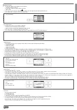
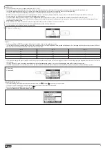
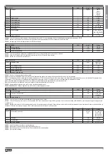
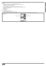
– The display shows the screen in the figure.
– Keys
change the selected digit.
– Key
confirms the digit and moves to the next.
– Enter numeric code, then move on the key icon.
– If the password code entered matches the User access code or the Advanced access code, then the relevant unlock message is shown.
– Once unlocked the password, the access rights last until:
• The device is powered off.
• The device is reset (after quitting the set-up menu).
• The timeout period of two minutes elapses without any keystroke.
– To quit the password entry screen, press
MENU
key.
SETTINGS LOCK
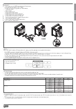
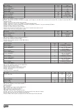
– On the DMG700 there are two DIP switches that are used to lock the access to parameter settings and / or to reset operations (commands menu).
– This DIP switches are placed in a way that they become unaccessible once the sealable terminal covers are mounted.
– To change switch position:
• Remove power supply to DMG700 and remove terminal covers (if mounted) and the 8-pole terminal block
• Using a small flat screwdriver, move the switches in the required position.
• Re-mount terminal blocks and terminal covers.
– The multimeter is supplied with the switches in unlocked position.
SW
POS
DESCRIPTION
SW1
OFF
Parameter settings allowed
ON
Parameter settings locked
SW2
OFF
Commands menu access allowed
ON
Commands menu access locked


