background image


Standard Chain Drive Mechanical Drawings 

The drawings and schematics in this section represent the mechanical layouts specific 

to standard, CF25, chain drive machines. 


43

Summary of Contents for Little David CF25

Page 1: ...LOVESHAW Little David Case Sealer CF25 Case Erector Version P Valid from October 2019 P N CF25 OM Operator sManual ...

Page 2: ... Loveshaw Inc 2206 Easton Turnpike PO Box 83 South Canaan PA 18459 Tel 1 800 962 2633 570 937 4921 Fax 570 937 4016 www loveshaw com Loveshaw Europe Unit 1 Newton Park West Portway Industrial Estate Andover Hampshire SP10 3SH ENGLAND Tel 264 357511 Fax 264 355964 ...

Page 3: ... correct and accurate at the time of its publication LOVESHAW reserves the right to change or alter any information or technical specifications at any time and without notice 2016 LOVESHAW All rights reserved Printed in the United States of America ...

Page 4: ...nsiderations Theory of Operation Theory of Operation for Chain Drive Machines Theory of Operation for Belt Drive Machines Operating Procedures Set Up Procedure Loading the Hopper Start Up Procedure Sequence of Operation Shut Down Procedure Maintenance Chain and Lug Drive Maintenance Side Belt Drive Maintenance CF25 Preventative Maintenance Schedule Spare Parts Troubleshooting Preliminary Checks Us...

Page 5: ...Drive Electrical Drawings 120 Volt 60 Hz Standard Belt Drive Electrical Drawings 240 Volt 60 Hz Non CE Compliant Standard Chain Drive Electrical Drawings 240 Volt 60 Hz Non CE Compliant Standard Belt Drive Electrical Drawings 240 Volt 50 Hz CE Compliant Standard Chain Drive Electrical Drawings 240 Volt 50 Hz CE Compliant Standard Belt Drive Electrical Drawings 230 Volt 3 Phase 60 Hz Standard Chain...

Page 6: ...v This space is intentionally blank Continue to next page ...

Page 7: ... to operate and maintain the case erector must read this manual to ensure safe operation as well as proper set up and maintenance throughout the life of the machine After reading this manual you will know how to perform the following functions How to install the machine How to operate the machine safely Troubleshooting and replacing of worn or defective parts Throughout this manual there are sever...

Page 8: ...rectly Observe the warnings and cautions below when using the Little David CF25 case sealer Within this manual on page 5 all safety labels are depicted with location and part numbers If a safety label is missing or not legible it must be replaced immediately Failure to follow safety labels can lead to injury or damage to the machine Instructions Instructions are requirements to system operations I...

Page 9: ...the machine is operating Warning Never place hands or body inside confines of the machine unless all power sources are locked out Warning Never wear jewelry loose clothing such as ties scarves etc and long hair must be pulled back when operating this machine Warning Never pull a jammed box out of the machine while it is in operation Warning Use caution when near cartridge knife or when threading t...

Page 10: ...his confirms that the emergency stop function is working correctly 5 Test all E Stops on the machine separately The overload motor relay must be tested every three months to confirm its operation This test can only be performed by a qualify technician since it requires the enclosure door to be opened 1 Connect the machine to the main electrical power source 2 Insure that the emergency stop pushbut...

Page 11: ...LOVESHAW AND IS TO BE TREATED BY YOU AS CONFIDENTIAL PRPRIETARY INFORMATION THIS DRAWING OR SUBJECT MATTER THEROF SHALL NOT BE REPRODUCED OTHER THAN FOR YOUR OWN USE OR TO BE DISCLOSED TO OTHER WITHOUT THE EXPRESSED WRITTEN CONSENT OF LOVESHAW AND WILL BE RETURNED TO LOVESHAW UPON REQUEST 1 18 2017 1 13 N A 1 20 2017 N A CF25T CF20 T FOOT PRINT SAFETY LABEL ASSY CF25 idw N A thaner REVISION HISTOR...

Page 12: ...eral parts of the machine The following diagram identifies the some key sections of the machine Chapter 3 Vertical Feed Assembly Box Opening Assembly Hopper Assembly Flap Folder Assembly Sled Assembly Main Drive Assembly Machine Guard Assembly Cartridge ...

Page 13: ... 60 with 15 amp dedicated service Operating speed Cases per Minute 10 for standard machines up to 15 c p m options available Air Requirement 14 SCFM 85 psi Maximum throughput based on maximum box range Machine box capacity Length 6 to 16 Width 6 to 14 3 5 minimum for side belt machines Height 4 to 12 NOTE Actual maximum dimensions are a function of each other and may be larger 7 ...

Page 14: ...Machine Options Spare Parts Kit Special Electronics Custom Color Casters Low Tape Alarm Low Hopper Alarm Box Jam Alarm Leg Extensions High Speed 12 14 15 8 ...

Page 15: ...remove the machine from the shipping skid Remove all fasteners and brackets holding the machine to the skid Step Two Transfer the machine from the shipping skid to the factory floor by lifting it with a fork lift Approach the machine from the side and carefully position the forks under the frame Locate the forks in the center on the machine so that they lift on the main frame flanges Take care tha...

Page 16: ... may result A similar condition will exist if poor electrical connections are made It is therefore worthwhile to make sure that everything is electrically correct Electrical polarity must be supplied to the machine exactly as shown on the electrical diagram Power must be supplied to the L1 side of the circuit and the L2 side will be neutral The compressed air supplied to the machine should be clea...

Page 17: ...This allows the vacuum cups to attach to the side wall of the box to be erected Solenoid valve SV9 is energized SV5 will be de energized pulling the blank out of the hopper Solenoid SV6 is energized and the vertical trolley will travel downwards towards the box opening area of the machine until finally reaching cylinder proximity switch Prox1 As the trolley is moving downward it will first trigger...

Page 18: ...ported by the minor flap folders Solenoid valves SV8 and SV9 are de energized The vacuum trolley moves up back to the hopper to get the next blank to be opened At the same time the box pusher is waiting for a signal from photoelectric sensor PE2 When PE2 is triggered it verifies the lugs are in position to receive the erected box Solenoid valve SV7 is energized Then the box pusher cylinder extende...

Page 19: ...nto position Prox3 is made activating SV2 rotating the box opening arm towards the blank When the box opening arm reaches the blank Prox6 is made activating SV8 supplying vacuum to the box opening vacuum cups After a timed delay SV2 deactivates allowing the opening arm to rotate outward opening the case When the case is opened Prox5 is made activating SV4 which extends the minor flap folder cylind...

Page 20: ...gth width and height with flaps up of box in inches see diagram Important Use scales and yellow pointers Due to changes in design for continual improvement the set ups depicted in the steps below might not be exact but similarities should exist Chapter 6 14 ...

Page 21: ...1 Hopper Near Side Set equal to width 2 A Hopper Far Side Use the blank flat box to set position Leave 1 4 of extra room Pointer and Scale Lock handle Lock handle 1 4 Gap ...

Page 22: ...3rd Vacuum Cup Adjust to widest position possible without cup hitting vertical box guide Tighten lock knobs securely 3 Vertical Trolley Stop Set equal to width Tighten securely Pointer and Scale Lock handle ...

Page 23: ...4 Box Opening Arm set equal to width arm in open position Adjust vacuum cup to land in center of major panel 5 Flap Folder Set to length Pointer and Scale Lock Handle ...

Page 24: ...6 Lug Drive Set to width 7 Sled Height set to erected box with top flaps up 8 Run one box in step manual mode to verify settings Pointer and Scale Crank Handle Pointer and Scale Lock knob ...

Page 25: ... and not leaning in any direction a The hopper can be reloaded without stopping the machine 7 Support the blanks with one hand and slide the gate back with the other 8 Take the last 5 or so blanks in the hopper and lean them toward the vacuum cups to support the remaining blanks 9 Load full bundles in the hopper Start Up Procedure 1 Close all guard doors and make sure all personnel are clear from ...

Page 26: ...g the cups to securely grip the blank The vacuum trolley pulls the blank downward into the forming area 6 When the trolley reaches the bottom vacuum is switched from the 3 rd outer cup to the cup on the box opening arm Simultaneously the arm swings in to grip the major panel of the box Immediately the arm reverses direction and returns to the home position causing the box to open 7 As the box is h...

Page 27: ...t position Wait until machine finishes processing box 2 Depress emergency stop push button Emergency Stop 1 Depress emergency stop push button 2 Remove any unmade or jammed boxes before restarting machine This space is intentionally blank Continue to next page 21 ...

Page 28: ... on the main drive NOTE A 5 16 18 x 3 bolt will be required This is not provided with the CF25 1 Locate the clearance hole on the side of the main drive that you wish to service Insert 5 16 18 x 3 bolt and begin to thread it into the hole See Figures 1 and 2 below 2 Tighten the bolt to release the desired amount of tension from the chain 3 Leave bolt tightened in place while the chain is serviced ...

Page 29: ...Figure 1 Inserting bolt into clearance hole Figure 2 Tightening bolt to compress tensioner springs Clearance Hole 5 16 18 x 3 Bolt Threaded Hole 23 ...

Page 30: ...s to the tensioning block For replacing a worn belt removal of the entire belt arm cover is necessary See Figures 2 and 3 below 2 Loosen the locking screw when adjusting belt tension 3 Use the nuts against the tensioning block to loosen and tighten the idler pulley 4 Replace the belt if necessary and properly tension the belt 5 Replace the belt arm door or entire belt arm cover Figure 3 Panels to ...

Page 31: ...Figure 4 Tensioning the idler pulley This space is intentionally blank Continue to next page Locking Screw Tensioning Block Nut Nut Idler Pulley 25 ...

Page 32: ... Check chain drive machines for chain tension on motor chain and lug drive Lug chains are automatically tensioned by spring loaded idlers If excessive slack is present chains should be replaced along with the sprockets and tensioning springs 2 Check that belt drive machines have proper belt tension and that rough top belt surfaces are not too worn 3 Check all bearings and bushings for wear 1 Check...

Page 33: ...Spare Parts See Appendix C for a complete list of recommended spare parts This space is intentionally blank Continue to next page 27 ...

Page 34: ...y to start a cycle The case erector can be stepped through each machine function by pushing the step push button For example when the machine is originally started in the test mode by pushing the step push button the vertical trolley vacuum cup assembly will extend toward the hopper By continually pushing the step button the machine will completely step through an entire machine cycle refer to mac...

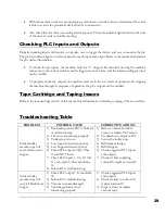
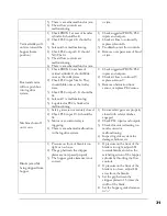
Page 35: ...idge and Taping Issues Refer to the tape cartridge section of this manual for all information referring to taping of the erected box Troubleshooting Table PROBLEM POSSIBLE CAUSE CORRECTIVE ACTION Vertical trolley vacuum cups will not extend toward hopper 1 Box backup sensor PE1 is blocked or malfunctioning 2 LS1 is not functioning properly 3 Trolley stop is loose 4 Low tape roll detected option 5 ...

Page 36: ...ning arm vacuum cup will not grip the blank 1 Check PLC output 6 7 it should be lit 2 Solenoid 8 and 9 are malfunctioning 3 Vacuum cup is damaged 4 Vacuum generator is not functioning properly 5 Vacuum hoses are clogged or damaged 6 Check PROX 6 on rotary actuator It should be lit 1 Check suggested PROX PLC inputs and outputs 2 Check air lines to solenoids 6 7 replace solenoids 6 7 3 Inspect repai...

Page 37: ...LC inputs and outputs 2 Check air lines to solenoid 7 replace solenoid 7 3 Remove obstruction from sensor or replace PE2 sensor Machine shuts off on its own 1 Safety gates are not securely closed 2 Check PLC input 10 It should be lit 3 Motor over current relay is triggering 4 There is a mechanical malfunction in the lug drive system 1 Ensure safety gates are properly closed with safety switches en...

Page 38: ...ing arm according to instructions in this manual Cylinders move slowly or erratically at start up 1 Damaged lines or loose fittings are leaking air 2 Slow start valve is not properly adjusted 1 Check for air leaks 2 Adjust start valve a Set regulator to 80 psi b Open slow start metering valve by turning adjuster out with a 3mm hex key Screw is found underneath the valve body c Test setting by star...

Page 39: ...WARRANTY For a detailed up to date warranty contact our customer service or view it on our website Chapter 9 33 ...

Page 40: ...MECHANICAL DRAWINGS AND SCHEMATICS Standard Universal Mechanical Drawings The drawings and schematics in this section represent the mechanical layouts common to all CF25 machines Chapter 10 34 ...

Page 41: ...TO BE DISCLOSED TO OTHER WITHOUT THE EXPRESSED WRITTEN CONSENT OF LOVESHAW ITW AND WILL BE RETURNED TO LOVESHAW ITW UPON REQUEST richm 3 1 2010 richm 4 12 2010 CF25T MACHINE OVERVIEW CF25 T CF25T idw ALARM LIGHT OPTIONAL BOX OPENING ASSEMBLY BOX OPENING ADJUSTMENT HANDLE MAIN LUG DRIVE ASSEMBLY MAIN LUG DRIVE ADJUSTMENT HANDLE DRIVE MOTOR AND REDUCER TOP SLED ASSEMBLY TAPE CARTRIDGE OPERATOR STATI...

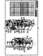
Page 42: ...BJECT MATTER THEROF SHALL NOT BE REPRODUCED OTHER THAN FOR YOUR OWN USE OR TO BE DISCLOSED TO OTHER WITHOUT THE EXPRESSED WRITTEN CONSENT OF LOVESHAW AND WILL BE RETURNED TO LOVESHAW UPON REQUEST 1 11 2017 1 6 N A 1 11 2017 N A MDACF25 MAIN DRIVE ASSY CF25 MDACF25 idw N A thaner Parts List DESCRIPTION PART NUMBER QTY ITEM CF25 DRIVE ASSY BASE MDACF25_BASE 1 1 CF25 DRIVE ASSY LEFT MDACF25_LEFT 1 2 ...

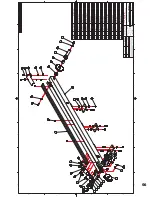
Page 43: ... 2011 BTACF25 BOX TRANSFER ASSEMBLY BTACF25 idw Parts List DESCRIPTION PART NUMBER QTY ITEM MOUNT LINEAR SHAFT CF20 0386 5 1 1 PLATE CYLINDER MOUNTING CF20 0489 3 1 2 ARM BOX TRANSFER CF20 0518 5 1 3 TEE PLATE BOX TRANSFER CF20 0531 4 1 4 FHCS M6 X 16 FFHMG016P10 2 5 HHCS M5 X 20 FHHMF020P10 4 6 HHCS M8 X 20 FHHMH020P10 8 7 7 16 20 HEX JAM NUT FHJNSMP 3 8 LOCK WASHER M5 FLWMFP 4 9 LOCK WASHER M8 F...

Page 44: ...F040P10 8 26 CASTLE NUT M10 x 1 5 SPH 1724 4 27 COTTER PIN 2 5mm X 20mm SPH 1725 4 28 SLED JACKING SCREW CF20 0882 4 4 29 N401 292 13 5 1 36 REVISION HISTORY REV DESCRIPTION DATE BY A RELEASED 3 9 2017 RTR ADJUSTMENT SCREW ASSEMBLY INSTRUCTIONS 1 INSERT JACKING SCREW THROUGH FLAT WASHER THEN THROUGH SLED FRAME CLEARANCE HOLE FROM TOP 2 SLIDE ANOTHER FLAT WASHER OVER END OF JACK SCREW BEFORE THREAD...

Page 45: ...ESSED WRITTEN CONSENT OF LOVESHAW ITW AND WILL BE RETURNED TO LOVESHAW ITW UPON REQUEST richm 2 22 2010 richm 3 9 2011 BPACF25 BLANK PUSHER ASSEMBLY CF25 T BPACF25 idw Parts List DESCRIPTION PART NUMBER QTY ITEM LINEAR SHAFT HOPPER CF20 0373A 4 2 1 GATE HOPPER CF20 0446 6 1 2 PIN HOPPER GATE CF20 0448 3 1 3 LEVER HOPPER GATE CF20 0542 4 1 4 HHCS M6 X 12 FHHMG012P10 4 5 HHCS M8 X 20 FHHMH020P10 1 6...

Page 46: ...Y 2 2 PANEL BRACKET CF20 0123 3 10 3 GUARD STATIONARY CF20 0333 6 1 4 GUARD SIDE UPPER CF20 0340 5 1 5 GUARD VERTICLE FEEDER CF20 0343 6 1 6 GUARD SPACER CF20 0344 3 8 7 PANEL SLIDING CF20 0418 4 2 8 SIDE CHANNEL SAFETY GATE CF20 0419 4 4 9 PLATE KEY MOUNTING CF20 0439 3 2 10 SPACER SAFETY SWITCH CF20 0440 3 2 11 TRACK SAFETY GATE CF20 0474 4 1 12 GUARD FRONT PANEL CF20 0539 5 1 13 GUARD MOTOR SID...

Page 47: ...RTICLE FEEDER CF20 0343 6 1 3 GUARD SPACER CF20 0344 3 8 4 PANEL SLIDING CF20 0418 4 2 5 SIDE CHANNEL SAFETY GATE CF20 0419 4 4 6 TRACK SAFETY GATE CF20 0474 4 1 7 GUARD FRONT PANEL CF20 0539 5 2 8 BHCS M5 X 10 FBHMF010P10 8 9 BHCS M5 X 12 FBHMF012P10 12 10 BHCS M5 X 20 FBHMF020P10 11 11 FHCS M5 X 12 FFHMF012P10 2 12 HEX DOME NUT M5 FHDNMFP 4 13 HEX NUT M5 FHFNMFP 12 14 LOCK WASHER M5 FLWMFP 16 15...

Page 48: ...Standard Chain Drive Mechanical Drawings The drawings and schematics in this section represent the mechanical layouts specific to standard CF25 chain drive machines 43 ...

Page 49: ...6 1 4 FRAME SIDE RIGHT CF20 0321 6 1 5 CENTER CHANNEL CF20 0322 6 1 6 BRACE TOP REAR CF20 0324 6 1 7 BRACE TOP SIDE LEFT CF20 0325 6 1 8 BRACE TOP SIDE RIGHT CF20 0326 6 1 9 BRACE CENTER HOPPER CF20 0327 6 3 10 UPRIGHT FRONT RIGHT CF20 0328 6 1 11 UPRIGHT FRONT LEFT CF20 0330 6 1 12 FRONT FRAME CF20 0331 6 1 13 BRACE TOP FRONT CF20 0332 6 1 14 MIDDLE BRACE CF20 0336 5 1 15 GUARD MOUNT CF20 0338 5 ...

Page 50: ...5 21 6 7 86 9 3523 57 2 29 6 1 6 72 75 7 28 6 21 17 3535 7 5 1 250 7 21 7 6 5 1 25 68 7 0 77 5 7 52 6 127 5 352 8 27 5 7 1 25 285 2 1 86 25 72 6 26 72 27 5 7 287 7 35 66 5 77 1 216 17 2 29 6 1 5 7851 72 29 6 8321 5 48 67 1 1 0 0 1 5 9 66 0 LGZ 1 WKDQHU 3DUWV LVW 6 5 37 21 3 57 180 5 47 7 0 5 9 66 6 0 B 6 5 9 66 7 0 B 7 5 9 66 5 7 0 B5 7 2 6 5 0 0 3 6 0 0 3 5 9 6 21 6725 5 9 6 5 37 21 7 5 6 575 45 ...

Page 51: ...INFORMATION THIS DRAWING OR SUBJECT MATTER THEROF SHALL NOT BE REPRODUCED OTHER THAN FOR YOUR OWN USE OR TO BE DISCLOSED TO OTHER WITHOUT THE EXPRESSED WRITTEN CONSENT OF LOVESHAW ITW AND WILL BE RETURNED TO LOVESHAW ITW UPON REQUEST dennisw 4 9 2015 VFACF25 with offset cups VERTICAL FEEDER ASSEMBLY CF25 VFACF25 with offset cups manual page idw Parts List DESCRIPTION PART NUMBER QTY ITEM CUP VC 10...

Page 52: ...AT WASHER M6 FFWMGP 5 28 FLAT WASHER M8 FFWMHP 6 29 FLAT WASHER 1 4 FFWSDP 2 30 HEX NUT M5 FHFNMFP 4 31 HEX NUT M6 FHFNMGP 7 32 HEX NUT M8 FHFNMHP 6 33 HEX NUT 3 8 16 FHFNSJP 1 34 HHCS M5 X 12 FHHMF012P10 4 35 HHCS M5 x 16 FHHMF016P10 1 36 HHCS M6 X 16 FHHMG016P10 8 37 HHCS M6 X 20 FHHMG020P10 4 38 HHCS M8 X 20 FHHMH020P10 10 39 HHCS M8 X 25 FHHMH025P10 2 40 HHCS M10 X 20 FHHMI020P88 2 41 LOCK WAS...

Page 53: ... 48 67 1 1 0 B 6 5 9 66 6 0 B 6 LGZ 1 WKDQHU 3DUWV LVW 6 5 37 21 3 57 180 5 47 7 0 1 5 1 2 7 187 3 7 7 5 5 9 6 7 25 217 6352 7 63 6352 7 63 5 1 1 5 5 1 66 0 5 8 5 5 02725 3 B 6 5 7 5 9 6833257 5 1 5 7 25 217 6 76 6 5 5 3 02817 1 3 7 5 2 5 7 5 9 6833257 5217 5 7 6 5 5 1 5 7 5 9 6833257 5 5 6352 7 6 6 5 1 3 187 3 7 5 7 5 5 6 0 0 3 0 02725 6833257 7 6 5 0 0 3 6 0 0 3 2 6 5 0 0 3 6 0 0 3 3 7 5 1 9 57 ...

Page 54: ...SHER SPH 1402 2 10 BRACKET LUG PHOTOEYE CF20 0484 4 1 11 STRIP SQUEEZER CF20 0506 4 1 12 BOX GUIDE LUG DRIVES CF20 0530 4 1 13 LOCK WASHER M8 FLWMHP 4 14 LOCK WASHER M6 FLWMGP 2 15 HHCS M6 X 16 FHHMG016P10 2 16 SHCS M5 X 0 8 X 20 LG FSHMF020P10 4 17 SHCS M5 X 0 8 x 40 LG FSHMF040P10 1 18 HHCS M8 X 25 FHHMH025P10 4 19 FLAT HEAD CAP SCREW M5 X 30 LG FFHMF030P10 5 20 SHCS M5 X 0 8 X 12 LG FSHMF012P10...

Page 55: ... 4 GUIDE STRIP LUG CHAIN CF20 0497 5 2 5 SPROCKET 203174 12 1 6 SPROCKET IDLER SPK 0121 1 7 BEARING FLANGED BRG 2004 1 8 SHOULDER BOLT 3 4 X 3 4 SPH 1401 1 9 SHIM WASHER SPH 1402 5 10 STRIP SQUEEZER CF20 0506 4 1 11 BOX GUIDE LUG DRIVES CF20 0530 4 1 12 HHCS M8 X 25 FHHMH025P10 4 13 SHCS M5 X 0 8 X 20 LG FSHMF020P10 5 14 LOCK WASHER M8 FLWMHP 5 15 FLAT HEAD CAP SCREW M5 X 30 LG FFHMF030P10 5 16 ST...

Page 56: ...ESHAW UPON REQUEST 1 6 2020 MDACF25 MAIN DRIVE ASSY CF25 MDACF25GB idw AMS Parts List DESCRIPTION PART NUMBER QTY ITEM CLAMP COLLAR 3 4 22201 2 1 SPROCKET 203174 12 1 2 BALL BEARING BEG 2004 2 3 MOUNTING PLATE GEARBOX CF20 0482 4 2 4 SHAFT VERTICAL DRIVE FIXED SIDE CF20 0569 4 1 5 SHAFT VERTICAL DRIVE ADJ SIDE CF20 0570 4 1 6 PLATE BEARING VERTICAL SHAFTS CF20 0573 4 2 7 FLAT WASHER M6 FFWMGP 8 8 ...

Page 57: ... 1 6 72 75 7 28 6 21 17 3535 7 5 1 250 7 21 7 6 5 1 25 68 7 0 77 5 7 52 6 127 5 352 8 27 5 7 1 25 285 2 1 86 25 72 6 26 72 27 5 7 287 7 35 66 5 77 1 216 17 2 29 6 7 1 5 7851 72 29 6 7 8321 5 48 67 ULFKP ULFKP 8 1 66 0 7 LGZ 3DUWV LVW 6 5 37 21 3 57 180 5 47 7 0 52 5 1 3 1 1 77 0 17 8 3 7 7 8 3 7 5 7 5 386 5 8 386 5 8 5 5 1 63 5 6 0 0 3 1 1 ORFN 1XW 1 16 3 6 6 6 6 5 9 6 21 6725 5 9 6 5 37 21 7 5 6 ...

Page 58: ... 21 17 3535 7 5 1 250 7 21 7 6 5 1 25 68 7 0 77 5 7 52 6 127 5 352 8 27 5 7 1 25 285 2 1 86 25 72 6 26 72 27 5 7 287 7 35 66 5 77 1 216 17 2 29 6 7 1 5 7851 72 29 6 7 8321 5 48 67 ULFKP ULFKP 6 8 1 66 0 63 6 LGZ 3DUWV LVW 6 5 37 21 3 57 180 5 47 7 0 52 5 1 3 1 1 77 0 17 8 3 7 7 8 3 7 5 7 5 386 5 8 386 5 8 5 5 1 63 5 6 0 0 3 1 1 ORFN 1XW 1 16 3 6 6 6 6 5 9 6 21 6725 5 9 6 5 37 21 7 5 6 50 3 57 2 3 ...

Page 59: ...0321 6 1 6 BRACE TOP FRONT CF20 0332 6 1 7 BRACE TOP REAR CF20 0324 6 1 8 GUARD MOUNT CF20 0338 5 1 9 MIDDLE BRACE CF20 0336 5 1 10 CENTER CHANNEL CF20 0322 6 1 11 SCALE BOX OPENING CF20 0430 3 1 12 BRACE TOP SIDE RIGHT CF20 0326 6 1 13 BRACE TOP SIDE LEFT CF20 0325 6 1 14 BRACE CENTER HOPPER CF20 0327 6 3 15 CHANNEL CENTER CF20 0512 6 1 16 MOUNTING POST TROLLEY STOP CF20 0537 5 1 17 EXTENSION DIS...

Page 60: ... BRACKET FLAP FOLDER CF20 0577 5 2 8 BRACKET CYLINDER FLAP FOLDER CF20 0578 4 2 9 PIVOT SHAFT FLAP FOLDER CF20 0581 3 2 10 RUBBER BUMPER F3MB 1 11 BHCS 10 32 X 1 2 FBHSD050P05 4 12 FLAT WASHER M6 FFWMGP 8 13 FLAT WASHER M8 FFWMHP 10 14 HEX NUT M8 FHFNMHP 4 15 HHCS M5 X 12 FHHMF012P10 1 16 HHCS M6 X 20 FHHMG020P10 10 17 HHCS M8 X 25 FHHMH025P10 4 18 HHCS M8 x 30 FHHMH030S10 4 19 HHCS M10 X 70 FHHMI...

Page 61: ... 5 7 52 6 127 5 352 8 27 5 7 1 25 285 2 1 86 25 72 6 26 72 27 5 7 287 7 35 66 5 77 1 216 17 2 29 6 7 1 5 7851 72 29 6 7 8321 5 48 67 ULFKP ULFKP 7 19 7 66 0 7 LGZ 3DUWV LVW 7 0 47 3 57 180 5 6 5 37 21 19 7 16 21 2 1 56 0 17 0 3 2 6 5 0 0 3 7 6 5 0 0 3 6 0 10 3 187 0 0 3 2 6 5 0 0 3 6 0 2 35 2 3 927 03 5 3 7 0 25 3 2 5 5 7 3 7 0 25 3 2 5 7 0 3 6 0 1 10 6 0 1 21 2 1 187 6 6 17 5 3 7 5 7 17 5 3 7 5 5...

Page 62: ...CF20 0564R 5 1 10 SPACER HOPPER GUIDE RAIL CF20 0565 3 2 11 VERTICAL GUIDE HOPPER RIGHT CF20 0566 5 1 12 VERTICAL GUIDE HOPPER LEFT CF20 0567 5 1 13 HUB HOPPER SPRING CF20 0575 3 2 14 COLLAR HOPPER LOCK CF20 0584 3 2 15 SPACER HOPPER COLLAR CF20 0585 3 2 16 BHCS M6 X 30 FBHMG030P010 2 17 FHCS M5 X 16 FFHMF016P10 12 18 FLAT WASHER M6 FFWMGP 4 19 HEX NUT M5 FHFNMFP 2 20 HEX NUT M8 FHFNMHP 4 21 HHCS ...

Page 63: ...SING CF20 0060 4 1 6 WASHER CLUTCH CF20 0062 3 2 7 PAD CHAIN CF20 0064 4 3 8 CHAIN GUIDE MOUNT CF20 0358 6 1 9 SPACER CYLINDER CF20 0360 4 1 10 HOUSING CLUTCH BEARING CF20 0561 4 1 11 SHAFT HOPPER DRIVE CF20 0563 4 1 12 CAM CLUTCH CL 1001 2 13 FHCS M5 X 12 FFHMF012P10 4 14 FLAT WASHER M8 FFWMHP 8 15 FLAT WASHER M10 FFWMIP 2 16 FLAT WASHER 3 8 FFWSFP 2 17 HEX NUT M8 FHFNMHP 8 18 HEX NUT M10 FHFNMIP...

Page 64: ...Standard Belt Drive Mechanical Drawings The drawings and schematics in this section represent the mechanical layouts specific to standard CF25 belt drive machines 57 ...

Page 65: ...1 4 FRONT FRAME CF20 0331 6 1 5 FRAME SIDE RIGHT CF20 0321 6 1 6 BRACE TOP FRONT CF20 0332 6 1 7 BRACE TOP REAR CF20 0324 6 1 8 GUARD MOUNT CF20 0338 5 1 9 MIDDLE BRACE CF20 0336 5 1 10 CENTER CHANNEL CF20 0322 6 1 11 SCALE BOX OPENING CF20 0430 3 1 12 BRACE TOP SIDE RIGHT CF20 0326 6 1 13 BRACE TOP SIDE LEFT CF20 0325 6 1 14 BRACE CENTER HOPPER CF20 0327 6 3 15 CHANNEL CENTER CF20 0512 6 1 16 MOU...

Page 66: ...OLLAR 3 4 202201 1 2 IDLER ROLLER 3SB2 3480 4 2 3 TEE NUT 3SB2 3651A 4 1 4 SHAFT 3SB2 3652 4 1 5 BEARING J122 2 6 LOCK WASHER M8 FLWMHP 1 7 HEX HEAD M8 x 75mm FHHMH075P10 1 8 SHAFT SPACER 3SB2 3467A 3 1 9 SHAFT SPACER 3SB2 3467D 3 1 10 TEE NUT 3SB2 3651 4 1 11 TENSIONER BLOCK 3SB2 3654 4 1 12 HEX JAM NUT M8 PLATED FHJNMHP 2 13 BELT BACKER CF20 0826 6 1 14 BELT RUB STRIP CF20 0827 4 2 15 BELT ARM C...

Page 67: ...OR SUBJECT MATTER THEROF SHALL NOT BE REPRODUCED OTHER THAN FOR YOUR OWN USE OR TO BE DISCLOSED TO OTHER WITHOUT THE EXPRESSED WRITTEN CONSENT OF LOVESHAW ITW AND WILL BE RETURNED TO LOVESHAW ITW UPON REQUEST dennisw 4 9 2015 VFACF25 with offset cups VERTICAL FEEDER ASSEMBLY CF25 VFACF25 with offset cups manual page idw Parts List DESCRIPTION PART NUMBER QTY ITEM BLOCK SUCTION CUP ARM CF20 0574 4 ...

Page 68: ...HER M6 FFWMGP 5 28 FLAT WASHER M8 FFWMHP 6 29 FLAT WASHER 1 4 FFWSDP 2 30 HEX NUT M5 FHFNMFP 4 31 HEX NUT M6 FHFNMGP 7 32 HEX NUT M8 FHFNMHP 6 33 HEX NUT 3 8 16 FHFNSJP 1 34 HHCS M5 X 12 FHHMF012P10 4 35 HHCS M5 x 16 FHHMF016P10 1 36 HHCS M6 X 16 FHHMG016P10 8 37 HHCS M6 X 20 FHHMG020P10 4 38 HHCS M8 X 20 FHHMH020P10 10 39 HHCS M8 X 25 FHHMH025P10 2 40 HHCS M10 X 20 FHHMI020P88 2 41 LOCK WASHER M5...

Page 69: ... 4 FFWSDP 2 6 80 20 EXTRUSION CF20 0101H 4 1 7 GUIDE UNIT SHORT CF20 0103 4 1 8 PLATE ROTARY ACTUATOR CF20 0407 4 1 9 ARM SUCTION CUPS CF20 0041 4 1 10 PILLOW BLOCK 5 8 BRG 1097 1 11 LEAD SCREW BOX OPENING CF20 0836 4 1 12 BRACKET NUT CF20 0408A 5 1 13 NUT PLATE RH THRD CF50 0135R 4 1 14 SPACER BOX OPENING ASSY CF20 0511 3 1 15 HAND KNOB HC 1046 2 16 REED SWITCH N612 2 17 LOCK WASHER M8 FLWMHP 20 ...

Page 70: ...POINTER FRONT FLAP FOLDER CF20 0545 3 1 6 SCALE 40 026 1 7 LOCK WASHER M10 FLWMIP 3 8 Hex Cap Screw M10 X 1 5 X 70 FHHMI070P88 3 9 LOCK WASHER M8 FLWMHP 4 10 ShoulderBolt 1 4 x 1 LG 10 24 THRD FSBSC100B08 2 11 LOCK WASHER M5 FLWMFP 2 12 HHCS M5 X 12 FHHMF012P10 1 13 HEX HD M8 x 30mm LG S S FHHMH030S10 4 14 NYLOCK NUT 10 24 FNLNSCP 2 15 SPEED CONTROL 90 DEG N400 183 4 16 LOCK WASHER M6 FLWMGP 4 17 ...

Page 71: ...ACF20 D 3_5 idw thaner Parts List DESCRIPTION PART NUMBER QTY ITEM ANVIL EXTENSION NARROW BOX CF20 0854 4 1 1 FOLDING BARS WELDMENT CF20 0015 5 1 2 CENTER PLATE CF20 0436 4 1 3 BRACKET CENTER PLATE CF20 0437 3 2 4 BRACKET CENTER PLATE RIGHT CF20 0522R 4 1 5 BRACKET CENTER PLATE LEFT CF20 0522L 4 1 6 FLAT WASHER M5 FFWMFP 12 7 SHCS M5 X 0 8 X 20 LG FSHMF020P10 12 8 LOCK WASHER M5 FLWMFP 12 9 HEX NU...

Page 72: ...X 0 8 X 20 LG FSHMF020P10 18 15 HEX NUT M5 FHFNMFP 2 16 SHCS M5 X 10 FSHMF010B10 2 17 LOCK WASHER M10 FLWMIP 4 18 HHCS M10 X 25 FHHMI025P88 4 19 TORSION SPRING SPR 1065R 1 20 TORSION SPRING SPR 1065L 1 21 SLIDE ENDING CF20 0117 4 2 22 STRIP HOPPER CF20 0451 4 2 23 SIDE RAIL HOPPER LEFT CF20 0564L 5 1 24 FLAT WASHER M6 FFWMGP 2 25 BHCS M6 X 30 FBHMG030P010 4 26 SPACER HOPPER GUIDE RAIL CF20 0565 3 ...

Page 73: ...3 3 1 8 40B24 1 CF20 0054 4 1 9 GUARD CHAIN CF20 0055 5 1 10 CYLINDER SPACER CF20 0360 4 1 11 PAD CHAIN CF20 0064 4 3 12 FLAT WASHER 3 8 FFWSFP 2 13 HH 3 8 16 x 1 LG FHHSJ100P08 2 14 FLAT WASHER M8 FFWMHP 8 15 HHCS M8 X 20 FHHMH020P10 4 16 LOCK WASHER M8 FLWMHP 10 17 HEX NUT M8 FHFNMHP 8 18 HEX HD M8 X 35 FHHMH035P10 6 19 FHCS M5 X 0 8 X 12 LG FFHMF012P10 4 20 FLAT WASHER M10 FFWMIP 2 21 LOCK WASH...

Page 74: ...Y INFORMATION THIS DRAWING OR SUBJECT MATTER THEROF SHALL NOT BE REPRODUCED OTHER THAN FOR YOUR OWN USE OR TO BE DISCLOSED TO OTHER WITHOUT THE EXPRESSED WRITTEN CONSENT OF LOVESHAW AND WILL BE RETURNED TO LOVESHAW UPON REQUEST 4 16 2018 1 2 N A 4 23 2018 N A BSACF25 BSACF25 BSACF25 idw N A thaner Parts List DESCRIPTION PART NUMBER QTY ITEM CYLINDER MOUNT CF20 0837 5 1 1 PIVOT SHAFT CF20 0838 4 1 ...

Page 75: ...8 1 4 N A 5 2 2018 N A hopper prox assembly hopper prox assembly idw N A dennisw Parts List DESCRIPTION PART NUMBER QTY ITEM GUARD MOUNT LEFT CF20 0892 1 1 HORZ TIE BAR CF20 0866 5 1 2 VERT BOX BAR CF20 0867 4 1 3 3 4 10 THREADED ROD CF20 0868 4 2 4 HEX JAM NUT 3 4 10 FHJMSRP 8 5 STEP AP203 FLWSJP 8 6 FLAT WASHER M5 FFWMFP 32 7 M5 NYLON LOCKING NUT S S FNLNMFS 16 8 SHCS M5 X 0 8 X 20 LG FSHMF020P1...

Page 76: ...Special Options Mechanical Drawings The drawings and schematics in this section represent the mechanical layouts of special options that can be custom ordered 67 ...

Page 77: ...MATIC DRAWINGS AND SCHEMATICS Standard Chain Drive Pneumatic Drawings The drawings and schematics in this section represent the pneumatic layouts specific to standard CF25 chain drive machines Chapter 11 68 ...

Page 78: ...69 ...

Page 79: ...EM MUFFLER VACUUM GENERATOR 402018 1 1 TEE BRASS 1 4 NPT H104 1 2 PLUG HEX 1 4 NPT H109A 3 3 MUFFLER 1 4 NPT N400 16 8 4 ELBOW 1 4 NPT X 1 4 PUSH LOC N400 26 3 5 CONNECTOR STRAIGHT 1 4 NPT X 1 4 TUBE N400 3 8 6 FITTING STR 1 4 NPT X 3 8 TUBE N400 8 6 7 VALVE SOL 5 2 N402 133 CE 8 8 MANIFOLD N402 133 M 1 9 VALVE AIR PILOTED N402 142 1 10 VACUUM GENERATOR N576 1 11 ELBOW 1 4NPT X 3 8 PUSHLOC PF 18 5...

Page 80: ...Standard Belt Drive Pneumatic Drawings The drawings and schematics in this section represent the pneumatic layouts specific to standard CF25 belt drive machines 71 ...

Page 81: ...72 ...

Page 82: ...X 3 8 TUBE N400 8 6 2 ELBOW 1 4NPT X 3 8 PUSHLOC PF 18 5 3 PIPE NIPPLE 1 4 X 2 1 2 PF 23 1 4 CONNECTOR STRAIGHT 1 4 NPT X 1 4 TUBE N400 3 8 5 VALVE SOL 5 2 N402 133 24VDC 8 6 MANIFOLD N402 133 M 1 7 MUFFLER 402018 1 8 VACUUM GENERATOR N576 1 9 PLUG HEX 1 4 NPT H109A 2 10 3 8 TEE BRASS PF 35 1 11 REDUCER 3 8 X 1 4 NPT BRASS PF 38 2 12 ELBOW 1 4 NPT X 1 4 PUSH LOC N400 26 3 13 BRASS NIPPLE H127 1 14...

Page 83: ...ELECTRICAL DRAWINGS AND SCHEMATICS Standard Universal Electrical Drawings The drawings and schematics in this section represent the electrical layouts common to all CF25 machines Chapter 12 74 ...

Page 84: ...Optional PLC AB MICRO850 NOTE Check the title block on panel assembly correlated to the specific machine before ordering replacement PLC Contact Loveshaw Customer Service for assistance if necessary This space is intentionally blank Continue to next page 75 ...

Page 85: ...120 Volt 60 Hz Standard Chain Drive Electrical Drawings The drawings and schematics in this section represent the electrical layouts related specifically to standard chain drive 120V rated machines 76 ...

Page 86: ...77 ...

Page 87: ...78 ...

Page 88: ...79 ...

Page 89: ...80 ...

Page 90: ...81 ...

Page 91: ...82 ...

Page 92: ...83 ...

Page 93: ...120 Volt 60 Hz Standard Belt Drive Electrical Drawings The drawings and schematics in this section represent the electrical layouts related specifically to standard belt drive 120V rated machines 84 ...

Page 94: ...85 ...

Page 95: ...86 ...

Page 96: ...87 ...

Page 97: ...88 ...

Page 98: ...89 ...

Page 99: ...90 ...

Page 100: ...91 ...

Page 101: ...92 ...

Page 102: ... in this section represent the electrical layouts related specifically to standard chain drive 240V rated machines that are not CE compliant NOTE Not all machines are CE compliant determine the specifications of the machine in order to reference the proper drawings and schematics within this manual 93 ...

Page 103: ...94 ...

Page 104: ...95 ...

Page 105: ...96 ...

Page 106: ...97 ...

Page 107: ...98 ...

Page 108: ...99 ...

Page 109: ...100 ...

Page 110: ...in this section represent the electrical layouts related specifically to standard belt drive 240V rated machines that are not CE compliant NOTE Not all machines are CE compliant determine the specifications of the machine in order to reference the proper drawings and schematics within this manual 101 ...

Page 111: ...in this section represent the electrical layouts related specifically to standard chain drive 240V rated machines that are CE compliant NOTE Not all machines are CE compliant determine the specifications of the machine in order to reference the proper drawings and schematics within this manual 102 ...

Page 112: ...103 ...

Page 113: ...104 ...

Page 114: ...105 ...

Page 115: ...106 ...

Page 116: ...107 ...

Page 117: ...108 ...

Page 118: ...109 ...

Page 119: ...110 ...

Page 120: ...in this section represent the electrical layouts related specifically to standard belt drive 240V rated machines that are CE compliant NOTE Not all machines are CE compliant determine the specifications of the machine in order to reference the proper drawings and schematics within this manual 111 ...

Page 121: ... 3 Phase 60 Hz Standard Chain Drive Electrical Drawings The drawings and schematics in this section represent the electrical layouts related specifically to standard chain drive 230V rated 3 phase machines 112 ...

Page 122: ...t 3 Phase 60 Hz Standard Belt Drive Electrical Drawings The drawings and schematics in this section represent the electrical layouts related specifically to standard belt drive 230V rated 3 phase machines 113 ...

Page 123: ...t 3 Phase 60 Hz Standard Belt Drive Electrical Drawings The drawings and schematics in this section represent the electrical layouts related specifically to standard belt drive 460V rated 3 phase machines 114 ...

Page 124: ...t 3 Phase 60 Hz Standard Belt Drive Electrical Drawings The drawings and schematics in this section represent the electrical layouts related specifically to standard belt drive 460V rated 3 phase machines 115 ...

Page 125: ......

Page 126: ......

Page 127: ......

Page 128: ......

Page 129: ......

Page 130: ......

Page 131: ......

Page 132: ......

Page 133: ......

Page 134: ......

Page 135: ......

Page 136: ......

Page 137: ......

Page 138: ......

Page 139: ...APPENDICES Appendix A Available Special Options BOX JAM DETECTION SENSOR P N A219 PF 13 LOW TAPE DETECTION SENSOR P N 303527 LOW HOPPER DETECTION SENSOR P N 302575 Chapter 13 116 ...

Page 140: ...Appendix B B LOC Instructions This space is intentionally blank Continue to next page 117 ...

Page 141: ...no longer be achieved 6 Continue to apply overtorque for 1 to 2 more passes This is required to compensate for a system related relaxation of locking screws since tightening of a given screw will always relax adjacent screws Without overtorquing an in nite number of passes would be needed to reach speci ed tightening torque 7 Reset torque wrench to speci ed torque Ma and check all locking screws N...

Page 142: ...Appendix C Recommended Spare Parts List This space is intentionally blank Continue to next page 119 ...

Page 143: ...1460 1 ROD END BEARING N400 183 1 FLOW CONTROL 1 8 NPT X 1 4 TUBE SPR 1065L 1 TORSION SPRING HOPPER SPR 1065R 1 TORSION SPRING HOPPER N591 1 FLOW CONTROL 1 4 NPT X 1 4 TUBE VC 1001 4 VACUUM CUP WITH NIPPLE HC 1046 1 KNURLED KNOB SPR 1059 2 EXTENSION SPRING HC 1045 1 RATCHET HANDLE N401 362 1 CYLINDER VERTICAL FEEDER STANDARD 10 CPM N401 363 1 CYLINDER VERTICAL FEEDER HIGH SPEED 10 CPM N402 133 2 S...

Reviews: