4 | Assembly
34
Basic Instructions for Use elisa 300-500
|
SW 2.09.x
|
Rev. 11
4.2.4.2
Removing the valve bar
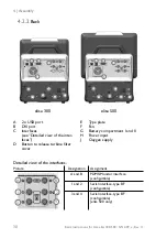
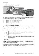
D
E
F
Actuate the respective release lever to be able to remove the individual elements
one after another (push release levers
E
and
F
backwards).
D
Release lever for expiratory flow sensor
E
Release lever for expiratory valve
F
Release lever for inspiratory valve
4.2.4.3
Installing the valve bar
The valve bar is assembled in reverse order. Introduce the modules into their
respective slots at a slight angle from below and push them upwards. Make sure
that the mechanical locks engage.
Warning
All valve bar modules must be reprocessed before a patient may
be connected to the ventilator.
Remark
Observe the correct sequence when inserting the inspiratory and
expiratory valve!
4.2.5
Battery
elisa 300 / elisa 500 can be equipped with a maximum of two batteries. One bat
-
tery is usually included in the delivery.
To insert or change a battery, remove the battery compartment cover on the
back of the ventilator. To do so, open the screws manually.
Summary of Contents for elisa 300
Page 3: ...elisa 300 elisa 500 Instructions for Use Basic Manual ...
Page 62: ...5 General information 60 Basic Instructions for Use elisa 300 500 SW 2 09 x Rev 11 ...
Page 217: ...elisa 300 elisa 500 Instructions for Use Supplement A Manoeuvres Functions Ventilation Modes ...
Page 351: ...CO2 Mainstream Sensor LeoCap Instructions for Use Supplement B ...
Page 379: ...Multi Gas Sensor LeoLyzer Instructions for Use Supplement C ...
Page 407: ...Pulse Oximetry and LeoClac Instructions for Use Supplement D ...
Page 437: ...Medical Equipment Interface elisa megs Instructions for Use Supplement F ...
Page 440: ...4 Instructions for Use Supplement F elisa megs Rev 03 This page is intentionally left blank ...

