background image

22

23

Sonar Operation | 

Elite X series

Sonar Operation | 

Elite X series

the distance from the transducer to the lowest part 

of the keel. If, for example, the keel is 3.5 feet below 

the transducer, it will be input as –3.5 feet.

Water speed calibration

Calibrates a paddlewheel speed sensor with speed 

data from a GPS source. 

Temperature calibration

Calibrates data from the transducer temperature 

sensor with data from a known temperature source 

to ensure the accuracy of temperature information. 

Reset water distance

Reset Water Distance to zero. 

Transducer Type

Selects the type of transducer model attached to 

your unit. 

Summary of Contents for ELITE-4X HDI

Page 1: ...Installation Operation manual Elite 4x Elite 5x Elite 7x Elite 9x Operation manual...

Page 2: ...right to do so without notice All features and specifications subject to change without notice Compliance Statements Lowrance Elite 4x Elite 5x Elite 7x and Elite 9x meets the technical standards in...

Page 3: ...harmful interference to radio communications However there is no guarantee that the interference will not occur in a particular installation If this equipment does cause harmful interference to radio...

Page 4: ...s 4 Page menus 4 Accessing the settings menu 5 Accessing menu items 5 Working with menus 6 Dialogs 6 Entering text 6 Fishing modes 7 Cursor 8 Advanced mode 8 Restore defaults 9 Pages 10 Sonar page 10...

Page 5: ...sh ID 19 Downscan options 20 Sonar settings 21 Installation 22 DownScan Operation 24 Trackback 24 DownScan menu 24 Ping speed 26 DownScan options 26 Settings 29 Settings menu 29 System 29 Set Language...

Page 6: ...ls Press the LIGHT POWER key to switch backlight levels Muting Audio Select Mute Audio from the System menu and press ENTER Unit Controls LIGHT POWER controls backlight level and turns unit on off KEY...

Page 7: ...that can only be accessed when those pages are displayed Setup wizard The Setup wizard will appear when the unit is turned on for the first time To choose your own settings do not run the setup wizar...

Page 8: ...U key is pressed The active panel is denoted by an orange border Accessing the Settings menu Accessing menu items The keypad and ENTER key are used to select menu items and open submenus Use the keypa...

Page 9: ...quire you to input text Working with menus There are several menu types used to make adjustments to options and settings including scrollbars on off features and dropdown menus Scrollbars Select the s...

Page 10: ...g preset packages of sonar settings geared to specific fishing conditions Switches keyboard between Alpha and QWERTY layout Switches letters to uppercase lowercase To input text 1 Use the keypad to se...

Page 11: ...temperature and bearings options NMEA 0183 Output NMEA 2000 Elite 7x and Elite 9x only Fishing Mode Options General Use 1000ft or less Coastal Shallow Water 60ft or less Shallow weedy bottoms Fresh W...

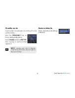
Page 12: ...d the display Press the PWR LIGHT key to access the Backlight dialog Select Standby and press ENTER Press any key to resume normal operation NOTE Leaving your unit in Standby mode when your boat is no...

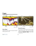
Page 13: ...screen Fish arches Surface Clutter Range scale Bottom Pages DownScan page The Downscan page shows the water column moving from right to left You can overlay downscan sonar on the conventional sonar pa...

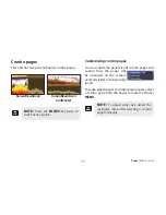
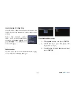
Page 14: ...ive panels Customizing combo pages You can adjust the panel size of combo pages and control how the pages will be arranged on the screen vertically side or horizontally over To make adjustments to com...

Page 15: ...Select the desired data and press ENTER 7 Press MENU and select Return to Overlays Press ENTER 8 Press MENU select Done Configuring and press ENTER Overlay Data Used to select data shown on the Sonar...

Page 16: ...ay data from the Configure Item Locations and Sizes dialog and press MENU The configuration menu will appear Data sources Used to select the network device that will supply source data for a selected...

Page 17: ...unit supports High CHIRP Medium CHIRP and Low CHIRP depending on the transducer CHIRP can be used with Lowrance conventional sonar transducers 50 200 kHz Low High CHIRP 83 200 kHz Medium High CHIRP T...

Page 18: ...starts to move in reverse Move the sonar history bar all the way to the right to resume normal sonar scrolling or press MENU and select Exit cursor mode Sonar Menu Press MENU from any sonar page to ac...

Page 19: ...or adjust ments Auto Sensitivity is turned on by default NOTE You can make minor 40 changes to sensitivity with Auto Sensitivity turned on You will have to turn it off to make significant adjustments...

Page 20: ...cies 50 kHz Best depth penetration with lower resolution 83 kHz Wider cone angle provides more bottom coverage and easy lure tracking 200 kHz Highest sensitivity and best tar get separation in shallow...

Page 21: ...rom other transducers When using fishing modes ping speed settings are optimized for the selected fishing conditions so in most cases adjustments are not necessary Sonar Options Noise Rejection Uses a...

Page 22: ...n make adjustments to DownScan overlay settings from the sonar page DownScan options are covered in more detail in the DownScan operation section Surface Clarity Surface Clarity reduces surfaceclutter...

Page 23: ...ning on the boat at the same time Overlay Data Allows you to select data to be displayed on top of the Sonar page Overlay data setup is covered in the Pages section NOTE The DownScan options menu will...

Page 24: ...onar settings will be visible on the sonar page WARNING Manual mode should only be used by advanced sonar users Manual Mode Restricts digital depth capability so the unit will only send sonar signals...

Page 25: ...des refer to the Basic Operation section Reset Fishing Mode Resets selected fishing mode to default settings That is useful when you want to clear settings adjustments made while using a fishing mode...

Page 26: ...r speed calibration Calibrates a paddlewheel speed sensor with speed data from a GPS source Temperature calibration Calibrates data from the transducer temperature sensor with data from a known temper...

Page 27: ...ssing the keypad to the left until the screen starts to move in reverse and the sonar history bar appears at the bottom of the screen Move the sonar history bar all the way to the right to resume norm...

Page 28: ...Adjusts the brightness ratio between light and dark areas on the screen making it easier to distinguish suspended objects from the background Adjust Accesses the Contrast adjustment scrollbar allowin...

Page 29: ...ital depth readings or you may receive incorrect depth information Ping Speed Controls the rate the transducer uses to send sonar waves into the water Ping speed adjustments can help reduce interferen...

Page 30: ...s the display to a split zoom view Surface Clarity Surface Clarity reduces surface clutter by decreasing the sensitivity of the receiver near the surface Surface Clarity set to Low Surface Clarity set...

Page 31: ...X series Overlay Data Allows you to select data to be displayed on top of the DownScan page Overlay data setup is covered in the Pages section Settings Accesses the Settings menu Refer to Sonar Setti...

Page 32: ...sts unit settings like language mute audio and advanced mode Settings Enables advanced features Refer to Advanced Mode on page 8 Displays software information System menu Restores settings and options...

Page 33: ...the unit back to default settings About Displays software information about this unit Before attempting a software update you can check the version of software your unit is using by accessing the Abo...

Page 34: ...h other display units on the network You will not be able to share existing waypoints Only waypoints created while the unit is connected to a NMEA 2000 network can be shared and only with units on tha...

Page 35: ...elect the source this unit will use for GPS data Device list Used to view data for devices connected to your NMEA 2000 network Simulator Simulates GPS and or sonar activity Simulations can be customiz...

Page 36: ...D 11 levels Communications NMEA 0183 Output Declaration of Conformity Part 15 103 FCC rules CE RTTE directive 1999 5 EC Power Transmit Power 250W RMS 30 000 PTP Power Requirement 12V Voltage Input 10...

Page 37: ...EA 0183 Output Declaration of Conformity Part 15 103 FCC rules CE RTTE directive 1999 5 EC Power Transmit Power Elite 7 250W RMS Elite 9 500W RMS Power Requirement 12V Voltage Input 10 to 17V Current...

Reviews: