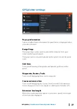
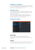
Safety depth
Sets the safety depth. Areas that are shallower than the safe
minimum depth are shaded. This option is only available if the
Safety shading palette is selected.
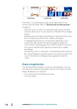
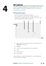
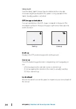
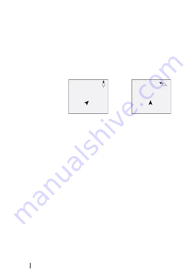
GPS image orientation
You can specify how the GPS image is rotated in the panel. The
orientation symbol in the panel’s upper right corner indicates the
north direction.
N
North up
N
Course up
North up
Displays the GPS plotter image with north upward.
Course up
The GPS plotter image direction is depending on if navigating or
not:
•
when navigating: the desired course is oriented up
•
if not navigating: the direction the vessel is actually traveling
(COG) is oriented up
Look ahead
Moves the vessel icon on the panel to maximize your view ahead of
the vessel.
26
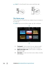
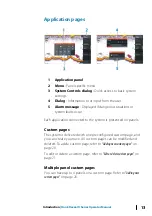
GPS plotter
| Hook Reveal X Series Operator Manual
Summary of Contents for Hook Reveal Series
Page 1: ...www lowrance com ENGLISH Hook Reveal X Series Operator Manual ...
Page 2: ......
Page 6: ...6 Preface Hook Reveal X Series Operator Manual ...
Page 10: ...10 Contents Hook Reveal X Series Operator Manual ...
Page 22: ...22 Customizing your system Hook Reveal X Series Operator Manual ...
Page 36: ...36 Waypoints routes and trails Hook Reveal X Series Operator Manual ...
Page 77: ......
Page 78: ... 988 12692 001 ...


