background image

| 41

Specifications | 

Link-6S User Guide

Specifications

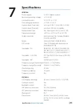
GENERAL

Power supply: 


12 V DC battery system

Nominal operating voltage:  + 13.6 V DC
Low battery alert: 


10.5 V DC +/- 0.5 V

Over voltage protection: 

> 15.8 V +/- 0.5 V

Current drain (Transmit): 

≤ 6 A @ 25 W / 1.5 A @ 1W (12 V DC) 

Current drain (Receive): 

Less than 450 mA in standby

Replacement Fuse:   

8 A, Glass type 3 AG; 32 mm (1.25”)

Temperature range:   

-20 ºC to +55 ºC (-4 ºF to 131 ºF)

Usable channels: 


International, USA, Canada, Weather  


   (country 

specific)

Mode: 


16K0G3E (FM) / 16K0G2B (DSC)

DSC mode:   


Class D (Global) with dual receiver    


   (individual 

CH70)

Standards - EU: 


EN60950-1, IEC 60529, EN 60945, EN  


301 843-1 V2.1.1, EN301 843-2 V2.1.1,  


EN 301 025 V2.1.1, EN 300 698 V2.1.1

Standards -   US/CAN:  

FCC Part 80, RSS-Gen Issue  4, RSS-182  


   Issue 

5

Standards - INT: 


AS/NZS 4415.1:2003

Frequency range (Transmitter): 156.025 - 157.425 MHz
Frequency range (Receiver):  156.050 - 163.275 MHz
Channel spacing: 


25 KHz

Frequency stability:   

± 5 ppm

Frequency control:   

PLL

PHYSICAL

LCD display (viewing): 

42 mm x 34 mm (1.65” x 1.3”), FSTN

Contrast control: 


Yes

Backlight control: 


Yes

VHF antenna connector: 

SO-239 (50 ohm)

GPS antenna connector: 

SMA (female)

Waterproof: 

  IPx7

Dimensions:  


W=166.7 mm (6.56”) x H=89.2 mm    


(3.5”) x D=161.4 mm (6.35”) - without  


   bracket

7

Summary of Contents for Link-6S

Page 1: ...ENGLISH Link 6S FixedMountVHF User Guide lowrance com ...

Page 2: ...truction manuals user guides and other information relating to the product Documentation may be translated to or has been translated from another language Translation In the event of any conflict between any Translation of the Documentation the English language version of the Documentation will be the official version of the Documentation This manual represents the product as at the time of printi...

Page 3: ...urther this transmitter must not be co located or operated in conjunction with any other antenna or transmitter Note This equipment has been tested and found to comply with the limits for a Class B digital device pursuant to Part 15 of the FCC Rules This equipment generates uses and can radiate radio frequency energy and if not installed and used in accordance with the instructions may cause harmf...

Page 4: ...hosen that the equivalent isotropically radiated power e i r p is not more than that necessary for successful communication Conformément à la réglementation d Industrie Canada le présent émetteur radio peut fonctionner avec une antenne d un type et d un gain maximal ou inférieur approuvé pour l émetteur par Industrie Canada Dans le but de réduire les risques de brouillage radioélectrique à l inten...

Page 5: ...elgium IS Iceland PT Portugal BG Bulgaria IE Ireland RO Romania CY Cyprus IT Italy SK Slovak Republic CZ Czech Republic LV Latvia SI Slovenia DK Denmark LI Liechtenstein ES Spain EE Estonia LT Lithuania SE Sweden FI Finland LU Luxembourg CH Switzerland FR France MT Malta TR Turkey DE Germany NL Netherlands UK United Kingdom GR Greece NO Norway Trademarks Lowrance and Navico are registered trademar...

Page 6: ...ry to obtain an MMSI number charges may apply If you are unsure who to contact consult your Lowrance dealer Note DSC distress calls generated by this radio are limited to the same range restrictions that apply to regular VHF transmissions The vessel sending a distress can only rely upon DSC if within range of a GMDSS Coast Radio Station Typical VHF range may be about 20NM though this varies greatl...

Page 7: ...DSC setup 23 Alarms 24 Reset 25 DSC call menu 25 DSC calls 27 Track buddy 28 Contacts 30 My channels 31 Shortcuts 32 Installation 32 Checklist 33 Installation options 33 Selecting a suitable mounting location 38 First startup configuration 41 Specifications 44 Channel charts 44 EU and INTERNATIONAL channel chart 52 USA channel chart 54 CANADA channel chart 57 Dimensional drawings ...

Page 8: ...marine VHF channel banks USA Canada International including weather channels where available model dependant Dedicated CH16 9 key for quick access to the priority international distress channel TRI key to select DUAL TRI scan Dedicated Wx Weather key DSC Digital Selective Calling capability that meets Global DSC Class D Standards Separate CH70 receiver included built in DISTRESS call button to aut...

Page 9: ...n the right side of the screen The black rectangle on the scroll bar indicates the highlighted options relative position in the list Press the Exit button to step backwards to the previous menu page or exit the menus completely Entry of alphanumeric data Rotate the channel knob to scroll through the alphanumeric characters Press channel knob to select and step to the next character To step backwar...

Page 10: ...traffic ie inner harbour Channel can only be received on DSC functionality is enabled DSC functionality is enabled auto switching is turned off EU models only must be enabled when in European inland waterways Low Battery warning activates at 10 5 V Channel bank is set to USA Channel bank is set to International Channels available depends on selected Country mode Channel bank is set to Canada Weath...

Page 11: ...urrent channel saved in My Channels 6 Track your buddy is enabled 7 Current channel will be skipped during a scan 8 Volume level indicator 9 Time derived from GPS UTC offset is applied 10 Latitude Longitude 11 Squelch level indicator 12 Channel number 2 or 4 digits 13 The USA channel bank is active 14 DSC functionality is enabled but autoswitch is off 15 Weather alert function is enabled ...

Page 12: ...control to adjust Which is currently selected is indicated by a small triangular arrow above the level bar for each option Turning the knob clockwise increases setting anti clockwise decreases it Volume control is common to internal and external speaker Long press to open SHORTCUTS 3 EXIT Press EXIT when navigating menus to clear incorrect entries to exit from a menu without saving changes and to ...

Page 13: ...ently skip over the channel The SKIP icon will show on the LCD for this channel To cancel a skipped channel select the channel while in normal mode non scan mode then press the ENT key the SKIP icon will disappear Repowering the radio also restores all skipped channels Press SCAN or EXIT while scanning is active to stop at the current channel and return to normal operation Long press SCAN from nor...

Page 14: ...o toggle between high 25 W or low 1 W transmission power for the entire channel bank The HI or LO selection is shown on the LCD Some channels allow only low power transmissions Error beeps will sound if attempting to change the transmission power while on one of these channels Some channels allow only low power transmissions initially but can be overridden to high power by pressing and holding H L...

Page 15: ...T SPEAKER ON OFF EXT SPEAKER ON OFF GPS TIME VESSEL CALLSIGN MENU TIMEOUT DSC FUNCTION X USER MMSI ATIS FUNCTION ON OFF SEA INLAND USE SEA INLAND ATIS MMSI INDIVIDUAL ACKN AUTO MANUAL POS ACKNOWLEDGE AUTO SWITCH ON OFF TEST ACKNOWLEDGE AUTO MANUAL RX DISTR WHILE OFF X DSC TIMEOUT WATCH DISPLAY SCAN RADIO SETUP DSC SETUP ALARMS GPS ALERT WX ALERT DSC ALARM RESET EU mode EU mode EU mode USA CAN mode...

Page 16: ...nels used in a MY CHANNELS scan Watch This menu is for choosing a watch mode to enable as well as selection of the watch channel Watch modes can be thought of as a channel scan on a subset of channels where scanned channels are listened to briefly every 3 seconds to determine if there is any active radio communication Note Watch modes are not available if ATIS mode is turned on Dual watch Select t...

Page 17: ...is turned off due to screen space constraints LOC Local Time is displayed below the time if a UTC Coordinated Universal Time offset has been entered otherwise UTC is shown in it s place if no offset has been applied POS display Select to switch ON or OFF the display of position provided from connected GPS COG SOG Select to switch ON or OFF the display of COG SOG provided from the selected GPS sour...

Page 18: ...o toggle between high 25 W or low 1 W transmission power for the entire channel bank The HI or LO selection is shown on the LCD Low power transmission draws significantly less current about 1 4 from the battery so is recommended for short range communication and where battery capacity is limited Note Some channels can t be switched to high power and will show LO regardless of power output setting ...

Page 19: ... used in DSC calls If POS Display is turned ON the latitude and longitude are shown on the screen with a prefix M indicating manual entry Note The manual entry is cleared if a real GPS position is received via the NMEA 0183 or Internal GPS depending on the GPS SOURCE setting GPS SOURCE Choose NMEA 0183 to have the radio listen for GPS data on its serial NMEA 0183 port Choose BUILT IN to use the in...

Page 20: ...fset Select TIME OFFSET to enter the difference between UTC and local time 15 minute increments can be used with a maximum offset of 13 hours Note Does not automatically adjust for Daylight Savings Time Time Format Select to toggle between 12 and 24 hour format Vessel call sign Select to enter vessel callsign Not used by radio purely for record keeping purposes Menu timeout An inactivity timeout c...

Page 21: ... agreement It should NOT be used outside these regions DSC functionality is not possible when ATIS is turned on Sea Inland mode EU ATIS radios only Toggles between DSC Sea and ATIS Inland modes Does not allow both to be selected at the same time ATIS ID EU ATIS radios only Enter an ATIS number to access the radio s ATIS functionality This unique identifier must be supplied a local radio spectrum a...

Page 22: ...red Auto channel switch AUTO SWITCH This setting only relates to All Ships and Group DSC calls When a DSC call is received it may include a request to change to a specific channel for subsequent communications With AUTO SWITCH set to ON the radio will switch channels after a 10 second delay The radio will also display options to switch immediately or reject the request and stay on the current chan...

Page 23: ...stress Select between NONE 5 MINS 10 MINS and 15 MINS default is NO TIMEOUT Non Distress Select between NONE 5 MINS 10 MINS and 15 MINS default is 15 MINS Alarms GPS alert The GPS alert is a warning to the user that the selected GPS source is not outputting valid position data It comprises of an audible alarm and visual alarm screen flash and warning text GPS alert function Turns ON or OFF all ale...

Page 24: ...nd OFF Screen flash Select between ON and OFF DSC Alarm The alert volume and screen flash for some incoming call types can be altered SAFETY ROUTINE and URGENCY calls can individually be set to have Alert volume HIGH LOW or OFF Screen flash ON or OFF Note it is not possible to alter distress call alert settings Reset Use this setting to return every setting to the factory defaults except all MMSI ...

Page 25: ...able when the DSC button is pressed DSC calls There are four call types as well as related options that can be accessed from this menu Individual Used to place a call to a single other vessel The call can be initiated by selected an existing vessel in the CONTACTS by entering in a new vessel s MMSI MANUAL or by selecting a vessel in the RECENT list When the SEND TO page is displayed turn the chann...

Page 26: ...on for the cancellation After a DISTRESS ACK is received the alert should be silenced and the reason for distress should be clearly stated pressing the PTT on the MIC and talking The following information if available is contained in the Distress Call Nature Of Distress if selected Position information the latest GPS or manual input position is held for 23 5 hours or until the power is turned OFF ...

Page 27: ...SI MANUAL or by selecting a vessel in the RECENT list As no voice communication is required no option is given to select a ship ship channel POS report Used to send a position report to the vessel being called DSC test Used to place a TEST call to a single other vessel The call can be initiated by selected an existing vessel in the CONTACTS by entering in a new vessel s MMSI MANUAL or by selecting...

Page 28: ...ddies in the Track buddy list that have been set to tracking ON The radio will show a screen indicating which buddy is being called If there is no acknowledgement the radio will retry the call after a few seconds Only one retry is made per tracking interval If tracking is already taking place the START TRACKING text is replaced with STOP TRACKING Interval The frequency that buddys are polled with ...

Page 29: ...this to create edit or delete up to 20 vessel groups which are stored in alphanumeric order Only a name and a Group Call ID GCID are required to set up a group A GCID always starts with 0 the remaining digits can be set to whatever the user desires All vessels intended to be in the same group must have a suitable DSC radio and have the identical GCID number entered Selecting an existing name in th...

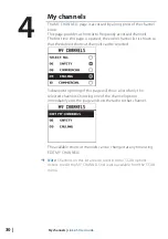
Page 30: ...o that the desired shortcut channels can be selected Subsequent opening of this page will show a list of only the selected channels Choosing one of the channel options immediately exits the page and sets the radio to that channel The available shortcut channels can be changed at any time using EDIT MY CHANNELS Note Channels on this list are also used in some SCAN options Access to edit the MY CHAN...

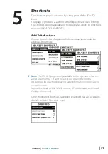
Page 31: ... shortcuts Choose from the list of options which menu options should be added as shourtcuts Note The MY VHF page is only available to the operator when en abled as a shortcut it can t be accessed via another menu It s purpose is solely for displaying radio information in one easy to access location It provides detail on the MMSI number GPS data status and Vessel Callsign if entered Once the desire...

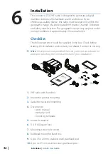
Page 32: ...ntenna is not provided Consult your Lowrance dealer for advice on selecting the correct antenna for your installation EN GL ISH In s t a l l a t i o n M a n u a l ba nd g co m EN GL ISH In s t a l l a t i o n M a n u a l ba nd g co m EN GL ISH In s t a l l a t i o n M a n u a l ba nd g co m EN GL IS H V H F R A D I O U s e r G u id e w w w ba nd g co m w w w sim ra d ya ch tin g co m w w w l o w r...

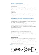
Page 33: ...asy access to the rear of the radio for connection to the 12 V DC electrical source the antenna and any network wiring Be at least 45 cms 1 5 from a compass to avoid creating magnetic deviation of the compass Have a suitable space close by for installing the microphone bulkhead mount Provide easy access to the controls on the front panel If intending to use the built in GPS antenna it must be in a...

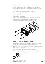
Page 34: ...ended Seek professional guidance if unsure Bracket installation The gimbal bracket provides an adjustable viewing angle with a 20º tilt range so ensure the selected mounting location will provide the desired viewing and operating conditions 1 Hold the bracket at the chosen location and use a soft pencil to mark the screw hole positions onto the mounting surface 2 Use a 3 mm 1 8 drill bit to drill ...

Page 35: ...a Phillips screwdriver secure the radio using the supplied 3 5x20 mm selftapping screws to the mounting location 8 Fit the mounting clips to cover the 4 mounting screws Install the hand mic bulkhead bracket 1 Hold the hand mic bulkhead bracket at the chosen location and mark the screw hole positions on the mounting surface Note Ensure that the microphone curly cable will comfortably reach this loc...

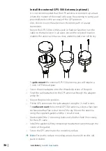
Page 36: ...00 antenna you will require a 1 inch 14 TPI thread pole Screw the pole adapter onto the threaded portion of the pole Feed the cable attached to the GPS antenna through the adapter and pole Mount the pole into position Fit the GPS antenna to the pole adapter using the 2 small screws To surface mount the external GPS 500 antenna select a flat clean surface area that has a clear view of the sky Mount...

Page 37: ...event the potential of a short circuit Warning never operate the radio without the antenna connected This may damage the transmitter The connectors are on the rear of the base unit as follows _ 1 Battery black connect to vessel s negative busbar 2 Battery red connect to vessel s 12 V DC via a switch panel or breaker comes with inline 8 amp fuse ready fitted 3 6 wires to be connected as follows 1 E...

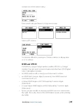
Page 38: ...t startup configuration The first time the radio is powered up the user is prompted to make a series of setting selections in order to allow the radio to perform to its full potential Some steps must be completed some are optional and can be completed later The steps are outlined below for reference Select the region and country the radio will be operated in Enter MMSI number if known or skip to n...

Page 39: ...er They are used on marine transceivers that have DSC Digital Select Calling functionality An MMSI remains with a vessel even if the vessel is sold on An MMSI has 9 numeric digits xxxxxxxxx Your MMSI must not commence with a 0 A Group MMSI begins with 0 followed by 8 numeric digits 0xxxxxxxx A Coast Station MMSI begins with 00 followed by 7 numeric digits 00xxxxxxx By law you are not able to chang...

Page 40: ...o implement common principles and rules for the safe carriage of people and goods on Inland Waterways The signatory countries are Austria Belgium Bulgaria Croatia the Czech Republic France Germany Hungary Luxembourg Moldova Montenegro the Netherlands Poland Romania Serbia the Slovak Republic and Switzerland Where a VHF is required on the inland waterways of the signatory countries this must be cap...

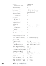
Page 41: ...C mode Class D Global with dual receiver individual CH70 Standards EU EN60950 1 IEC 60529 EN 60945 EN 301 843 1 V2 1 1 EN301 843 2 V2 1 1 EN 301 025 V2 1 1 EN 300 698 V2 1 1 Standards US CAN FCC Part 80 RSS Gen Issue 4 RSS 182 Issue 5 Standards INT AS NZS 4415 1 2003 Frequency range Transmitter 156 025 157 425 MHz Frequency range Receiver 156 050 163 275 MHz Channel spacing 25 KHz Frequency stabil...

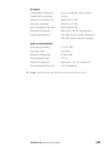
Page 42: ...es Tri watch Yes Favourite channel scan Yes All scan Yes User programmable MMSI Yes MMSI and NAME directory Yes 20 numbers group TRANSMITTER Frequency error 1 5 KHz Output power 25 W 23 2 1 W 0 8 0 2 Transmitter protection Open short circuit of antenna Max Frequency deviation 5 Spurious harmonics Hi Lo 0 25 µ W Modulation Distortion 3KHz 10 S N at 3KHz Deviation 40 dB Audio Response at 1KHz 1 to 3...

Page 43: ... more than 68 db Residual noise level more than 40 db unsquelched Audio output power 2 W with 8 ohm at 10 distortion 4 W with 4 ohm external speaker BUILT IN GPS RECEIVER Receiving frequency 1575 42 MHz Tracking code C A code Number of channels 72 channels Horizontal accuracy 10 m Position fixing time Warm start 30s Cold start 90s Position update interval 1 second typical Note Specifications are s...

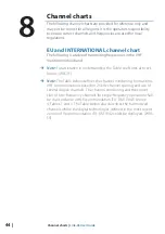
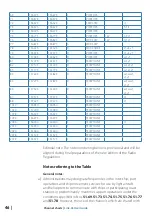
Page 44: ...te For assistance in understanding the Table see Notes a to zz below WRC 15 Note The Table below defines the channel numbering for maritime VHF communications based on 25 kHz channel spacing and use of several duplex channels The channel numbering and the conver sion of two frequency channels for single frequency operation shall be in accordance with Recommendation ITU R M 1084 5 Annex 4 Tables 1 ...

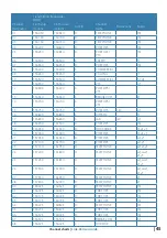
Page 45: ...700 S PORT OPS VTS 15 156 750 156 750 S PORT OPS 1W g 16 156 800 156 800 S DISTRESS f 17 156 850 156 850 S SAR 1W g 18 156 900 161 500 D PORT OPS m 19 156 950 161 550 D SHIP SHORE t u v 20 157 000 161 600 D PORT OPS t u v 21 157 050 161 650 D PORT OPS w y 22 157 100 161 700 D PORT OPS w y 23 157 150 161 750 D TELEPHONE w x y 24 157 200 161 800 D TELEPHONE w ww x y 25 157 250 161 850 D TELEPHONE w ...

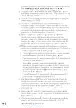
Page 46: ... S TELEPHONE z 1019 156 950 156 950 S TELEPHONE 1020 157 000 157 000 S TELEPHONE 1078 156 925 156 925 S TELEPHONE 1079 156 975 156 975 S TELEPHONE 2006 160 900 160 900 S TELEPHONE r 2019 161 550 161 550 S TELEPHONE 2020 161 600 161 600 S TELEPHONE 2078 161 525 161 525 S TELEPHONE 2079 161 575 161 575 S TELEPHONE Editorial note The note numbering below is provisional and will be aligned during fina...

Page 47: ...maritime mobile distress and safety automatic identification system AIS and data exchange frequencies especially the channels 06 13 15 16 17 70 AIS 1 and AIS 2 nor the technical characteristics set forth in Recommendation ITU R M 489 2 for those channels implementation of 12 5 kHz channel interleaving and consequential national requirements shall be subject to coordination with affected administra...

Page 48: ... single frequency channels subject to coordination with affected administrations The following conditions apply for single frequency usage The lower frequency portion of these channels may be operated as single frequency channels by ship and coast stations Transmission using the upper frequency portion of these channels is limited to coast stations If permitted by administrations and specified by ...

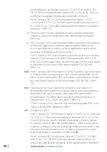
Page 49: ...0 161 925 MHz corresponding to channels 24 84 25 85 26 and 86 are identified for the utilization of the VHF Data Exchange System VDES described in the most recent version of Recommendation ITU R M 2092 These frequency bands may also be used for analogue modulation described in the most recent version of Recommendation ITU R M 1084 by an administration that wishes to do so subject to not causing ha...

Page 50: ...annels 24 84 25 and 85 may be merged in order to form a unique duplex channel with a bandwidth of 100 kHz in order to operate the VDES terrestrial component described in the most recent version of Recommendation ITU RM 2092 WRC 15 mm Transmission on these channels is limited to coast stations If permitted by administrations and specified by national regulations these channels may be used by ship s...

Page 51: ... M 1842 The frequency bands 157 025 157 175 MHz and 161 625 161 775 MHz corresponding to channels 80 21 81 22 82 23 and 83 can also be used for analogue modulation described in the most recent version of Recommendation ITU R M 1084 by an administration that wishes to do so subject to not claiming protection from other stations in the maritime mobile service using digitally modulated emissions and ...

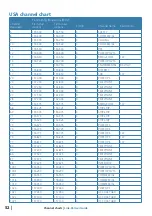
Page 52: ... 350 161 950 D TELEPHONE 28 157 400 162 000 D TELEPHONE 67 156 375 156 375 S BRIDGE COM 1W 68 156 425 156 425 S SHIP SHIP 69 156 475 156 475 S SHIP SHIP 71 156 575 156 575 S SHIP SHIP 72 156 625 156 625 S SHIP SHIP 73 156 675 156 675 S PORT OPS 74 156 725 156 725 S PORT OPS 75 156 775 156 775 S PORT OPS 1W 76 156 825 156 825 S PORT OPS 1W 77 156 875 156 875 S PORT OPS 1W 84 157 225 161 825 D TELEP...

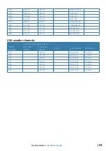
Page 53: ...075 157 075 S RESTRICTED 1082 157 125 157 125 S RESTRICTED 1083 157 175 157 175 S RESTRICTED USA weather channels Transmitting frequencies MHz Channel designator From ship stations From coast stations S D R Channel name Restrictions WX1 162 550 R NOAA WX1 RX ONLY WX2 162 400 R NOAA WX2 RX ONLY WX3 162 475 R NOAA WX3 RX ONLY WX4 162 425 R NOAA WX4 RX ONLY WX5 162 450 R NOAA WX5 RX ONLY WX6 162 500 ...

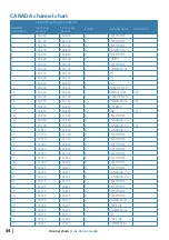
Page 54: ...ERCIAL 1W 16 156 800 156 800 S DISTRESS 17 156 850 156 850 S SAR 1W 18 156 900 161 500 D TELEPHONE 19 156 950 161 550 D CANADIAN CG 20 157 000 161 600 D CANADIAN CG 1W 21 157 050 161 650 D CANADIAN CG 22 157 100 161 700 D TELEPHONE 23 157 150 161 750 D TELEPHONE 24 157 200 161 800 D TELEPHONE 25 157 250 161 850 D TELEPHONE 26 157 300 161 900 D TELEPHONE 27 157 350 161 950 D TELEPHONE 28 157 400 16...

Page 55: ...6 950 156 950 S CANADIAN CG 1020 157 000 157 000 S PORT OPS 1021 157 050 157 050 S RESTRICTED 1022 157 100 157 100 S CANADIAN CG 1024 157 200 157 200 S PORT OPS 1025 157 250 157 250 S PORT OPS 1026 157 300 157 300 S PORT OPS 1027 157 350 157 350 S CANADIAN CG 1061 156 075 156 075 S CANADIAN CG 1062 156 125 156 125 S CANADIAN CG 1063 156 175 156 175 S TELEPHONE 1064 156 225 156 225 S RESTRICTED 106...

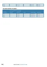
Page 56: ...2086 161 925 R PORT OPS RX ONLY Canada weather channels Transmitting frequencies MHz Channel designator From ship stations From coast stations S D R Channel name Restrictions WX1 162 550 R CANADA WX Rx only WX2 162 400 R CANADA WX Rx only WX3 162 475 R CANADA WX Rx only ...

Page 57: ... 57 Dimensional drawings Link 6S User Guide Dimensional drawings 166 7 mm 6 56 60 mm 2 36 123 4 mm 4 86 161 4 mm 6 35 89 2 mm 3 51 114 2 mm 4 5 9 ...

Page 58: ......

Page 59: ......

Page 60: ... 988 11181 003 ...

Reviews: