50 |
Installation |
Link-9 User Guide
•
Route the cable to your VHF transceiver unit, adding any necessary
extension cables.
•
Connect the cable from the GPS antenna to the GPS connector
(SMA) on the VHF transceiver as shown below.
Connect the radio wiring
All wiring on the radio should be done with the vessel power supply
turned off. While radio power is polarity protected, the fuse will blow
if the connection is made the wrong way round. Ensure any unused
bare wires are isolated from each other, to prevent the potential of
a short circuit. If using the NMEA 2000 connection, ensure network
topology rules are followed closely.
!
Warning: never operate the radio without the antenna
connected. This may damage the transmitter.
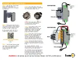
The connectors are on the rear of the base unit, as follows:
+_
T
T
1
2
3
4
7
5
6
8
NMEA
0183
Hailer
speaker
External
speaker
GPS
antenna
Chart plotter
VHF
antenna
GPS
antenna
Battery (+)
12 V DC (nom)
Battery (-)
1.
Battery - (BLACK): connect to vessel’s negative busbar.
2.
B (RED): connect to vessel’s 12 V DC, via a switch panel or
breaker (comes with inline 8 amp fuse ready fitted).


