29
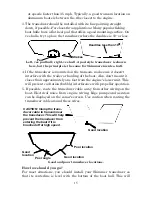
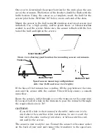
Once you've determined the proper location for the unit, place the sen-
sor on the transom. The bottom of the bracket should be flush with the
hull's bottom. Using the sensor as a template, mark the hull for the
screws' pilot holes. Drill four 1/8" holes, one in each end of the slots.
Mount the sensor to the hull using #8 stainless steel wood screws (not
included). Use a
high quality, marine grade
above- or below-waterline
sealant to seal the screws. Make sure the sensor is flush with the bot-
tom of the hull and tighten the screws.
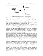
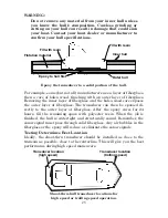
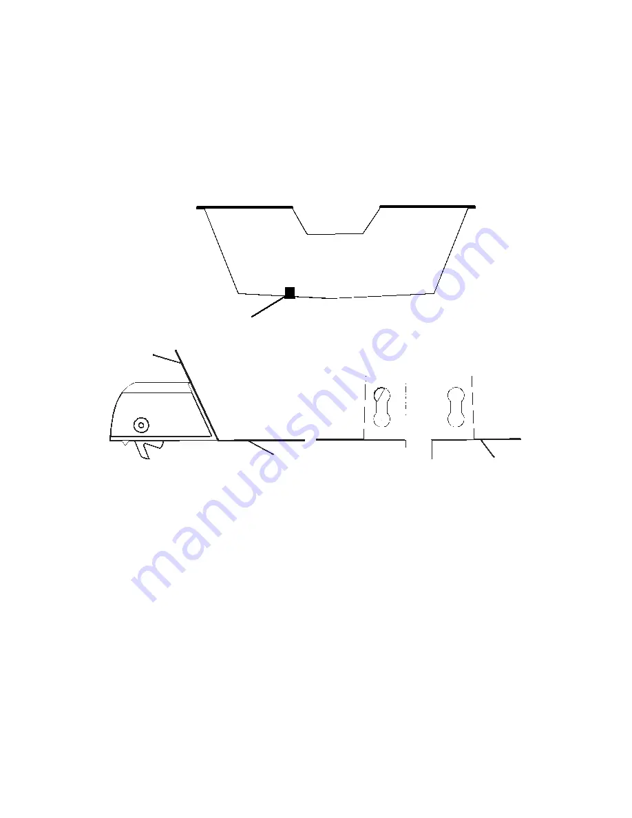
Stern view showing good location for mounting sensor on transom.
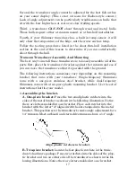
Speed sensor mounting configuration:
side view (left) and rear view (right.)
If the base of the transom has a radius, fill the gap between the tran-
som and the sensor with the sealant. This will help ensure a smooth
water flow.
Route the sensor's cable through or over the transom to the sonar unit.
If you need to drill a hole in the transom to pass the connector through,
the required hole size is 7/8".
CAUTION:
If you drill a hole in the transom for the cable, make sure it is lo-
cated above the waterline. After installation, be sure to seal the
hole with the same marine grade above- or below-waterline seal-
ant used for the screws.
The sensor is now ready for use. Connect the sensor to the sonar socket
on the back of your unit and connect the transducer to the speed sen-
Good location
Transom
Bottom of hull
Bottom of hull
Summary of Contents for LMS-332C
Page 20: ...12 Notes ...
Page 52: ...44 Notes ...
Page 61: ...53 Notes ...
Page 68: ...60 Notes ...
Page 106: ...98 Notes ...
Page 110: ...102 Notes ...
Page 190: ...182 Notes ...
Page 208: ...200 Notes ...
Page 212: ...204 Notes ...
Page 213: ...205 Notes ...

